5 Get File
from Drive
button
If a .cam le exists for the selected prole, this
function transferss it from the servo drive and
shows a Save File window to select the location
to save the le to.
6 Open in
CAM Editor
button
If a .cam le exists for the selected prole, this
function transfers it from the servo drive to a
temporary location and opens it with the CAM
Editor.
7 Send
Congu-
ration
button
Sends the conguration (Execution, Master
Position, and Slave Position) to the servo drive.
8 Slave
Position
congu-
ration
Contains 2 radio buttons that specify if the
selected prole should be executed with slave
absolute or slave relative position. When the
sub-tool is opened, the option is read from the
servo drive and the radio buttons are selected
accordingly.
9 Master
Position
congu-
ration
Contains 2 radio buttons that specify if the
selected prole should be executed with
master absolute or master relative position.
When the sub-tool is opened, the option is
read from the servo drive and the radio
buttons are selected accordingly.
10 CAM Parsing
Info
Visualizes the download info and parsing info
for the selected prole index:
•
After a download procedure, shows its
result.
•
After a parse procedure on the servo drive,
shows text corresponding to the parsing
state status code on the servo drive.
•
When clicking on the Refresh button, the
ISD Toolbox reads the parsing state status
code from the servo drive and updates the
text.
•
When reading the CAM prole from the
servo drive and saving it as a .cam le,
shows the location of the saved le.
11 Execution
area
Contains 2 radio buttons that specify if the
selected prole should be executed in cyclic or
non-cyclic mode.
12 Loading info Text eld showing the loading state for the
selected prole.
Illustration 5.84 CAM Prole Management
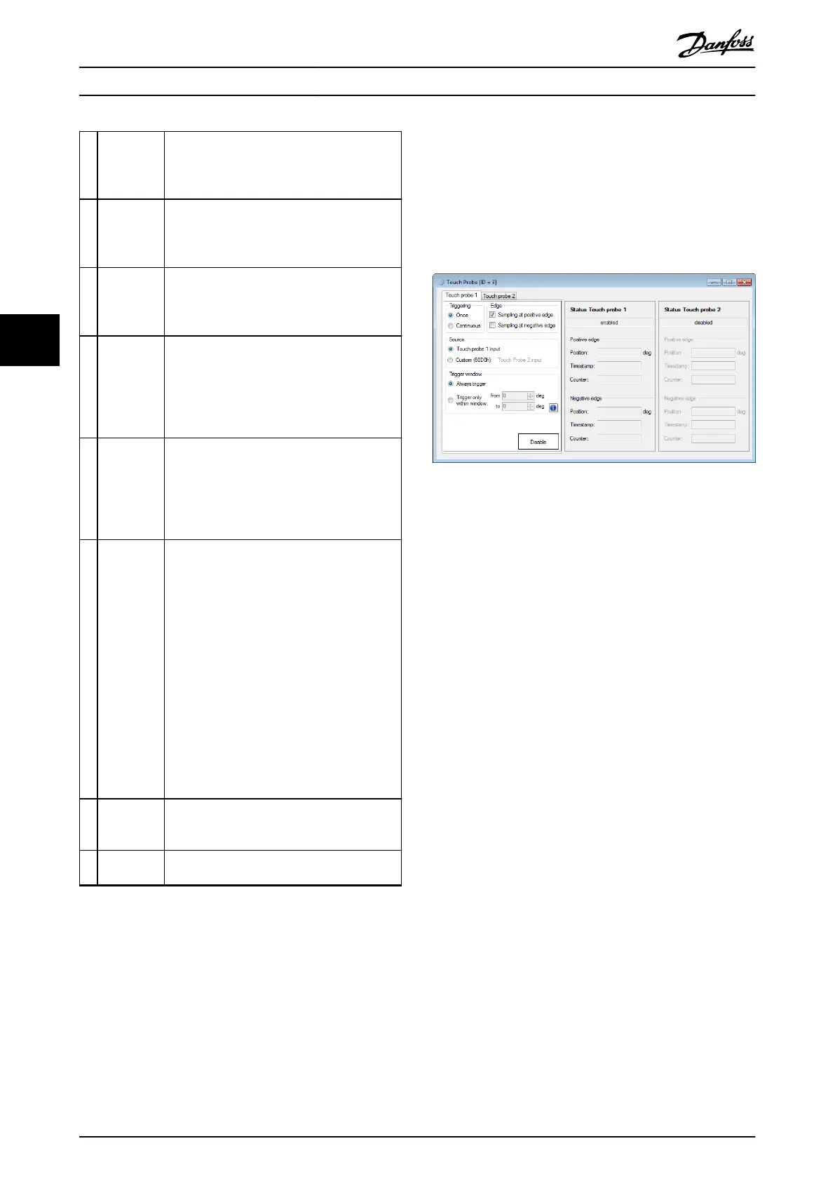
5.7.9 Touch Probe (Servo Drive only)
The Touch Probe sub-tool congures the settings of the
touch probe functionality of the servo drive. There are 2
touch probe channels available that can be used in
parallel. See chapter 2.5.2 ISD Touch Probe for more
information on the touch probe functionality.
Illustration 5.85 Touch Probe Sub-tool
5.7.10 SAB Control (SAB only)
The SAB Control sub-tool visualizes and controls the SAB
state machine and therefore can be used to enable or
disable the UDC and U
AUX
voltage on the lines, and to
reset an error. The sub-tool can only be used in cyclic
mode (direct communication) as it sends the commands to
the SAB in the form of process data objects (PDO).
The SAB Control consists of the 6 SAB states; every state is
assigned a distinct color and has a list of navigable
successor states and a list of automatic transitions that can
only be triggered by the SAB rmware itself. The SAB
states, along with their respective colors, are described in
chapter 5.5.2 Device Environment Window.
Illustration 5.86 depicts the SAB Control sub-tool containing
the
dened SAB states. The active state is highlighted with
its dened state color. The directly navigable successors of
the active state are accessible (enabled) but the others are
not accessible (disabled).
Operation with ISD Toolbox
VLT
®
Integrated Servo Drive ISD
®
510 System
158 Danfoss A/S © 01/2017 All rights reserved. MG36D102
55

 Loading...


