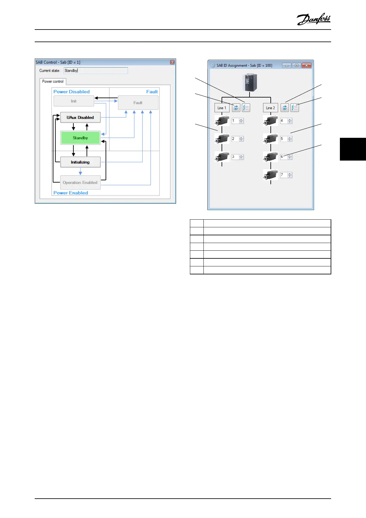
Illustration 5.86 SAB Control
At the top of the SAB Control window, a text
eld shows
the current state of the SAB.
The available manual transitions to navigable successors
are shown as black arrows and the possible automatic
transitions are visualized as thin light blue arrows.
In order to transition from a state to a successor, click on
the desired successor state. Only valid successors are
accessible in the SAB Control window, preventing an invalid
transition command being sent to the SAB.
5.7.11 SAB ID Assignment via Ethernet
POWERLINK
®
(SAB only)
The SAB ID Assignment sub-tool controls the Ethernet
POWERLINK
®
-specic SAB functionality to set the IDs of the
servo drives on the network and to visualize the topology
of the network. ID assignment is not required for
EtherCAT
®
(see chapter 6.1.1 EtherCAT
®
).
The SAB ID Assignment sub-tool graphically shows the SAB
and its 2 lines. Initially, both lines are empty. After clicking
on the Refresh button for 1 of the 2 lines, the connected
drives and their corresponding IDs on the line are
determined and shown. The lines are shown vertically and
each servo drive is shown together with its Ethernet
POWERLINK
®
ID.
Illustration 5.87 visualizes the SAB ID Assignment sub-tool,
showing a topology with 3 drives on line 1 and 4 drives on
line 2.
1 Auto-assign line 1
2 Refresh line 2
3 Auto-assign line 2
4 Servo drives on line 2
5 Servo drive ID
6 Servo drives on line 1
7 Refresh line 1
Illustration 5.87 SAB ID Assignment
Each servo drive is visualized with a corresponding drive
image and a numeric eld showing its ID.
The Auto-assign line buttons for both lines perform an
automatic assignment of all servo drive IDs on the
respective line. Clicking on an Auto-assign button opens a
separate window that prompts for the starting ID.
Afterwards the automatic ID assignment procedure is
initiated.
It is also possible to set the device IDs of
specic servo
drives on any line manually by setting the desired ID in the
text eld next to each servo drive.
When changing the value of a drive ID eld, 2 additional
buttons appear next to the ID eld (see Illustration 5.88).
These are:
•
Apply changed ID: Applies the set ID on the servo
drive.
•
Revert to changed ID: Undoes the changes to the
ID eld and reverts the value back to the actual
ID of the servo drive.
Operation with ISD Toolbox Programming Guide
MG36D102 Danfoss A/S © 01/2017 All rights reserved. 159
5 5

 Loading...


