SECTION 5 - REMOVAL - REFITTING OF THE MAIN ENGINE COMPONENTS
41
CURSOR SERIES
Print P4D32C006 E Base - 03/2015
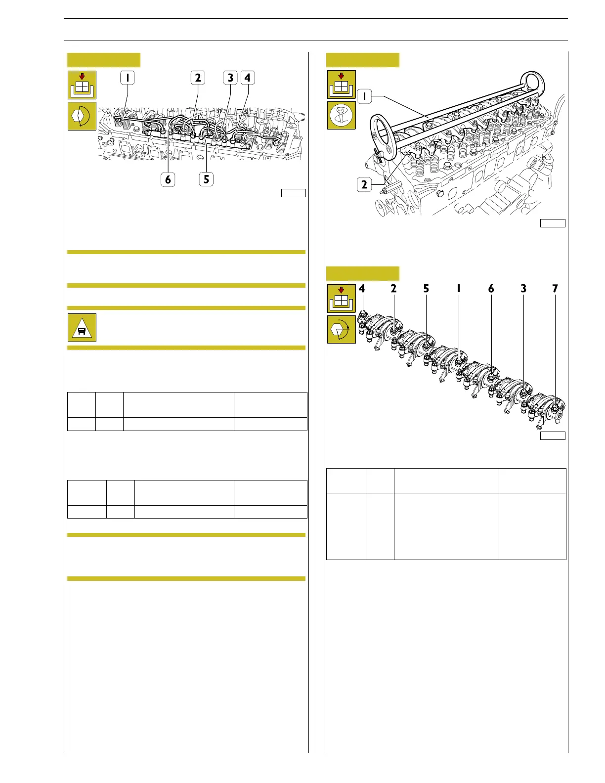
Figure 117
225054
Connect the high pressure fuel pipes and tighten the fittings by
hand in the sequence (1, 2, 3, 6, 5, 4) to the rail and the
injectors.
NOTE Before tightening the fittings to torque make sure
that the pipes (1) are not touching each other.
The high pressure fuel pipes must be replaced at each
disassembly.
Complete injector assembly operations by tightening the
bracket fastening screws to the torque shown in the table.
Ref.
No. Description
Tightening
torques
(-) 6 Screws M8 X 1.25 X 45 35 ± 2 Nm
Complete assembly of the high pressure fuel pipes (1, 2, 3, 6,
5, 4) by first tightening the injector side fittings and then those
ontherailsidetothetorqueshowninthetable.
Ref.
No. Description
Tightening
torques
(1 - 6) 12 Fittings M16 X 1.5 42.5 ± 2 Nm
NOTE before refitting the rocker-arm shaft assembly,
make sure that all the adjustment screws have
been fully unscrewed.
Figure 118
225045
Apply the tool 99360553 (1) to the rocker arm shaft (2) and
mount the shaft on the cylinder head.
Figure 119
α
227746
Screw the screws in four steps as follows:
Ref.
No. Description
Tightening
torques
(1 - 7) 7
Screws M16 X 1.5 X 76
Step 1 25 Nm
Step 2 60 Nm
Step 3 80 Nm
Step 4 60˚
Tighteningsequence:1-2-3-4-5-6-7.