Laser unit
1/6
2. Replacement and adjustment of parts
26710
26710
Laser unit
Replacing and adjusting the position of the laser unit
!
!!
! Precautions for laser unit replacement
IMPORTANT
• If you replaced the laser unit, items shown below are necessary in returning the defective unit.
!
!!
! Procedure
1. Open the printer top cover.
2. Remove paper advance unit 2.
☞26550
3. Remove the processor loading unit.
☞26610
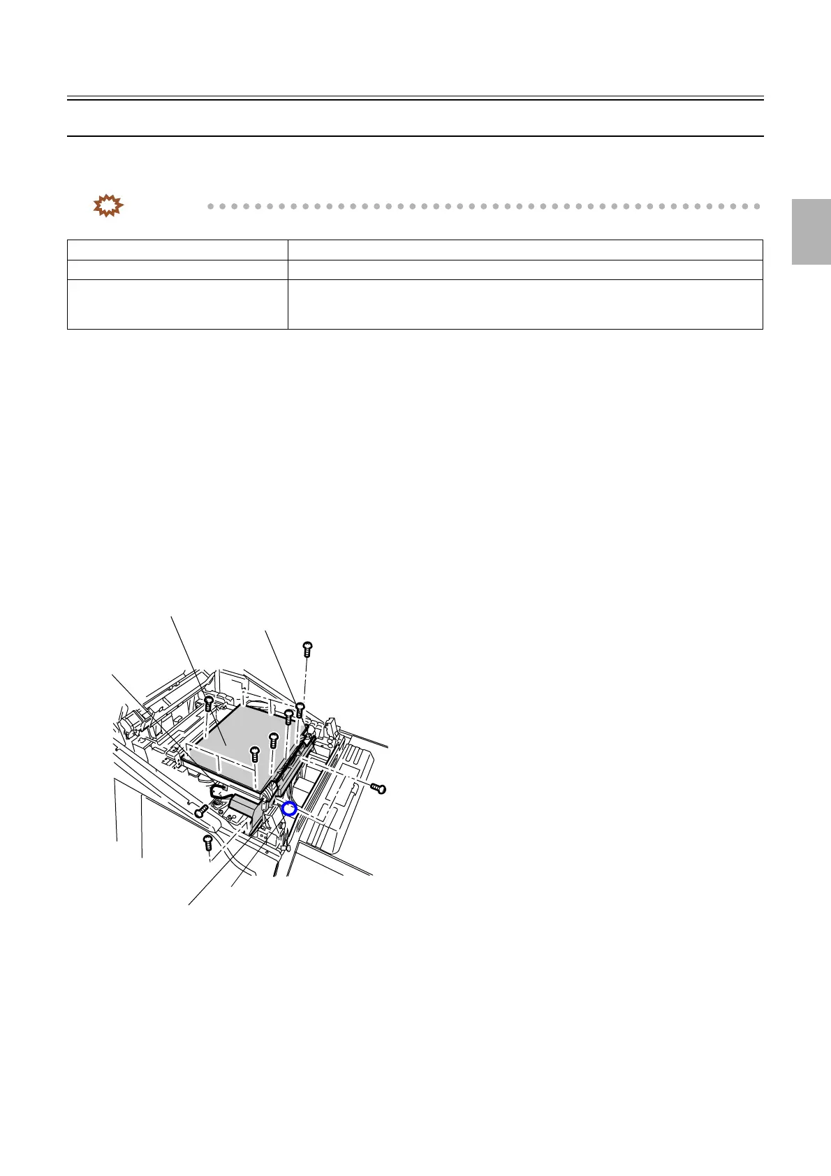
4. Remove the wiring cover. (Loosen two screws.)
5. Remove the PCB cover. (ten screws)
6. Remove laser control box cooling fan 1. (one screw)
7. Disconnect the ground wire. (one screw)
8. Disconnect the connector(s).
J/P1619 (Laser control box cooling fan 1)
Laser unit Defective laser unit
Sample print The print where the abnormal color can be checked
Backup data Backup data when the problem occurred
Make a backup copy of all the data in Reading and Writing Data.
☞35400
PCB cover
Laser control box cooling fan 1
Wiring cover
J/P1619
Ground wire
G085223
Distributed by: minilablaser.com