Explanation of PCBs (Processor section)
1/1
6. Electrical parts
66211
66211
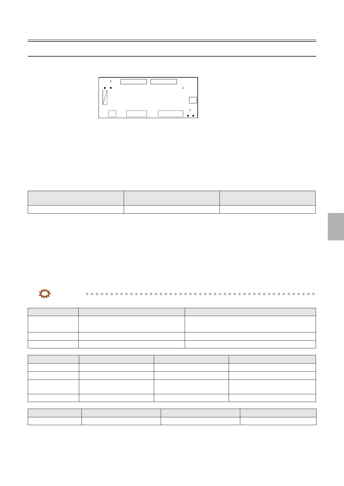
Processor I/O PCB 2 (J391490)
!
!!
! Function
• Controls the Paper Advance Motor, Calibration Plate Advance Motor, Pressure Change Solenoid and Colorimeter Cooling
Fan of the colorimeter unit.
• Controls the Dryer selection solenoid 2 of the dryer rack.
!
!!
! Reference
!
!!
! Adjustments and precautions for PCB replacement
• None
!
!!
! Unused connector
Not in use
!
!!
! Component parts table
IMPORTANT
• Although sometimes the test pins are unmounted, the test points can be used for the measurement.
Layout diagram Symptom due to the poor connection of
wiring
Symptoms of fuse blowout
☞63200 ☞4203 ☞4252
LED No. Purpose Status
LED1 Checks the set attaching condition of the
colorimeter unit
• On when the colorimeter unit is attached.
• Off when the colorimeter unit is removed.
LED2 DC+24 V input check On when the power supply is turned on.
LED3 DC+5 V input check On when the power supply is turned on.
Test point No. Purpose Measurement with voltmeter Remarks
TP1 Ground Possible
TP2 Ground Possible Not mounted
TP3 DC+5 V power supply
measurement
Possible Not mounted
TP4 DC+24 V voltage measurement Possible Not mounted
Fuse No. Rating Purpose Remarks
F70 T5A/127 V DC+24 V protection
F70
P906P903 P904
P905
LED2
TP1
TP4
LED1
LED3
TP3
TP2
G085224
Distributed by: minilablaser.com