Positions of electrical parts (Processor section)
1/2
6. Electrical parts
63315
63315
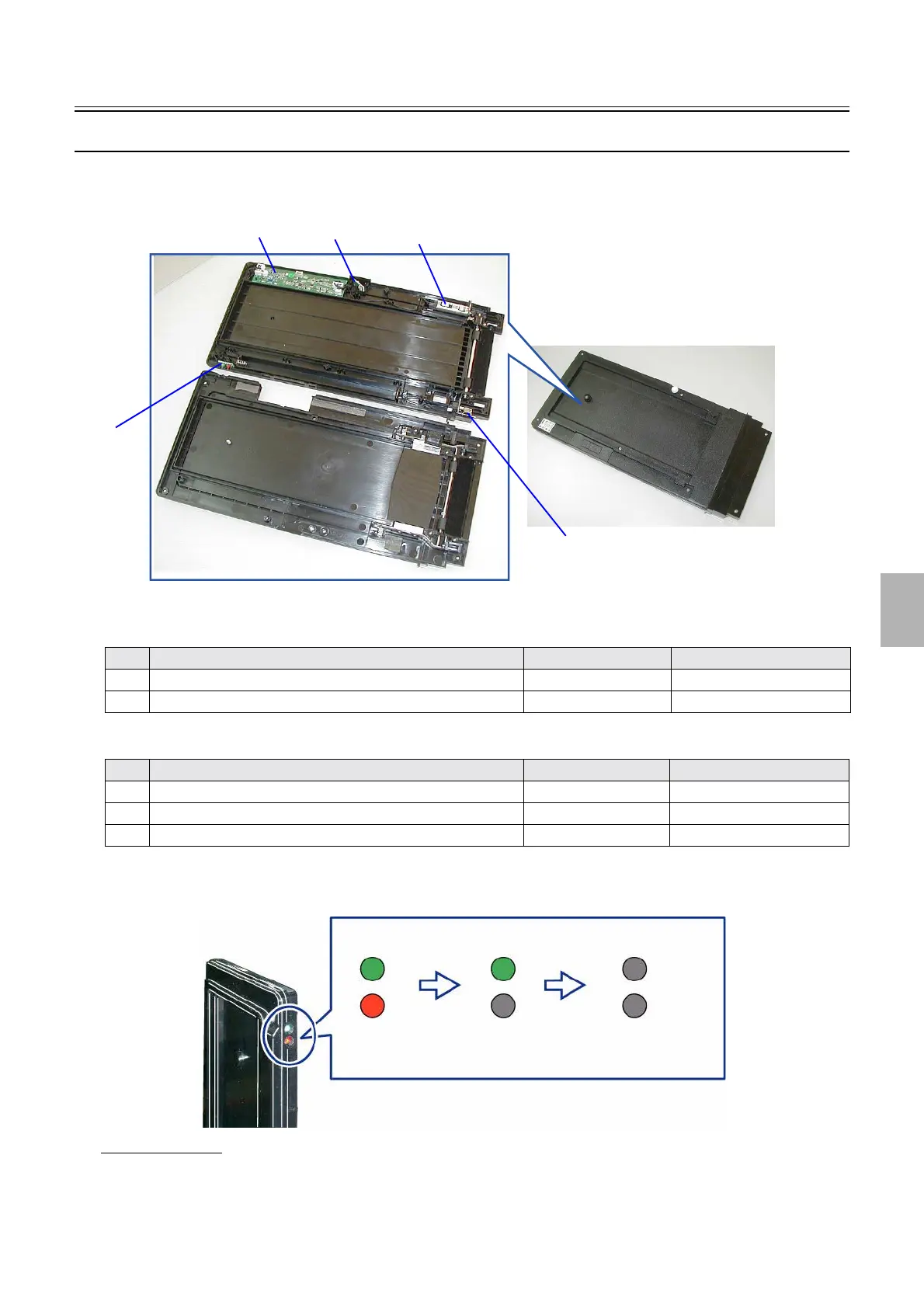
Control strip auto loading unit (positions of PCBs and electrical parts)
!
!!
! Layout diagram
(Position of PCBs)
(Position of electrical parts)
!
!!
! (Checking of the status lamp)
When the auto loading unit is inserted, the green and red lights, as show in the figure, turn on from off.
If the light blinked
If an error occurs, the light blinks for about 60 seconds.
• If the red light blinked
Not communicating normally.
Start over the process following the procedure below.
No. Name Manual No. Remarks
1 Control strip driver PCB
☞66810
2 Infrared communication unit ☞66830
No. Name Symbol Remarks
3 Control strip feed motor M1
4 Control strip holder detection switch LM1
5 Status lamp LED1
1
4
5
2
3
G085189
Green: lighting
Red: lighting
Green: lighting
Red: not lighting
Green: not
lighting
Red: not lighting
When inserted
In ten seconds after
G088042
Distributed by: minilablaser.com