4. Troubleshooting
4203
5/7
4203
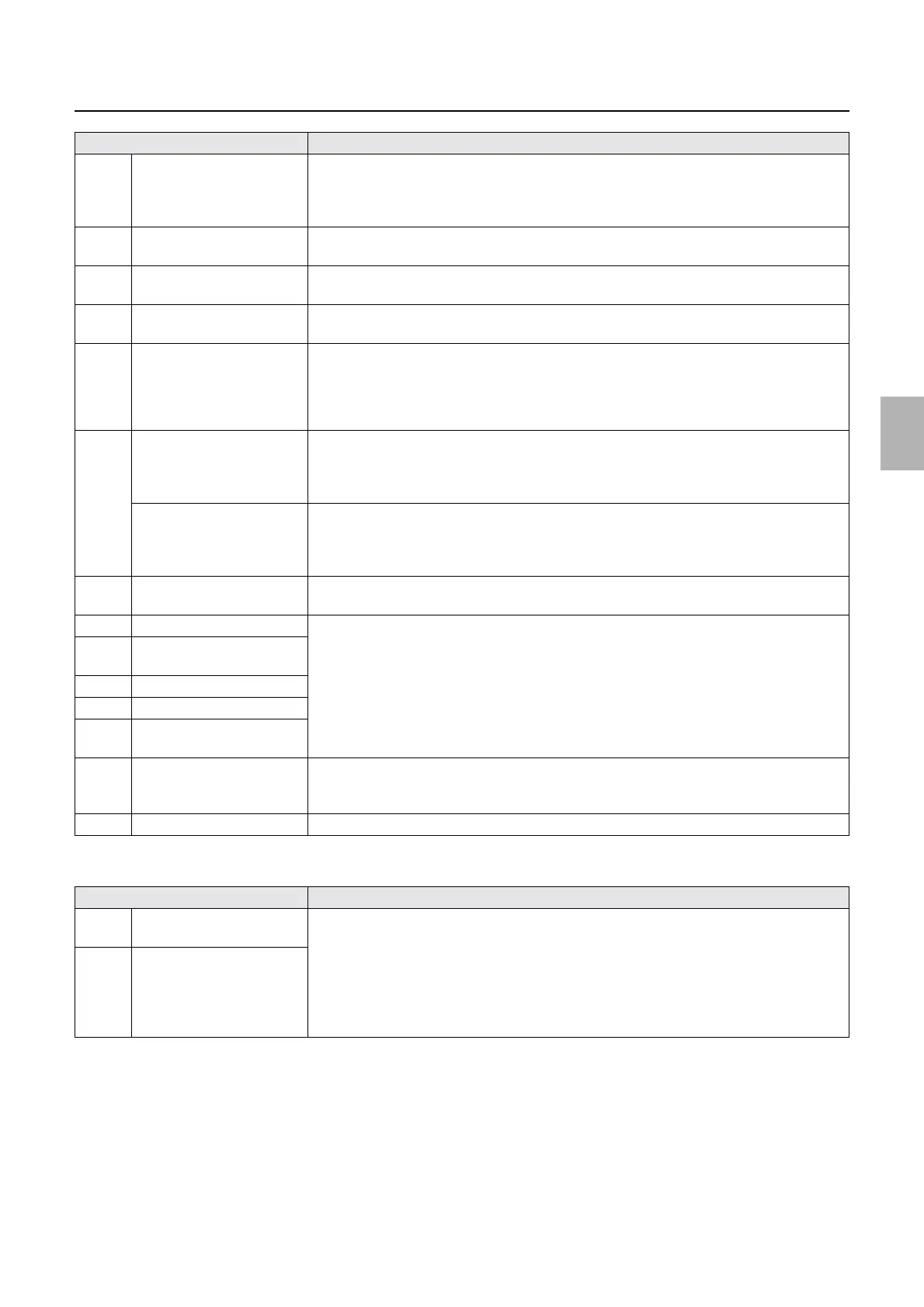
Diagnosis appendix for the failures: Symptom due to the connection failure of wiring
!
!!
! Processor power supply 1 (PS1)
J/P650 Connects to the processing
solution float switches CD,
BF, STB1, STB2, STB3, and
STB4
The following error message is shown.
• No.05508-00000 The processing solution level is too low. occurs.
• No.05532-00000 The Processing Solution Safety Thermostat has activated. occurs.
J/P651 Connects to the interlock
switch (dryer cover).
No.00506-00000 Close the Dryer Cover. occurs.
J/P652 Connects to the interlock
switch (processor top cover).
No.00507-00000 Close the Processor Top Cover. occurs.
J/P653 Connects to the dryer safety
thermostat.
No.05533-00000 The Dryer Safety Thermostat has activated. occurs.
J/P654 Connects to processor I/O
PCB 1 and processor I/O
PCB 2.
The following error message is shown.
• No.05508-00000 The processing solution level is too low. occurs.
• No.05532-00000 The Processing Solution Safety Thermostat has activated. occurs.
• No.05533-00000 The Dryer Safety Thermostat has activated. occurs.
J/P655 Connects to the drive motor.
(QSS-
3701/3702/3703/LP7500/LP7
600)
No.05550-00000 Drive Motor has stopped. occurs.
Connects to the drive motor
driver PCB.
(QSS-
3704/3705/LP7700/LP7900)
No.05550-00000 Drive Motor has stopped. occurs.
J/P656 Connects to processor power
supply 1.
Power supply cooling fan 1 rotates, but both the printer and processor do not start.
J/P657 Connects to the dryer heater. The dryer heater does not turn on.
J/P658 AC power supply jumper
(dryer heater)
J/P659 Connects to the dryer heater.
J/P660 Connects to the dryer heater.
J/P661 AC power supply jumper
(dryer heater)
J/P662 Connects to the processing
solution heaters CD, BF and
STB
The processing solution heaters CD, BF and STB do not turn on.
J/P663 Connects to the ground wire Unconfirmed
Connector No. Symptom
J/P791 Power supply from the
processor relay PCB
Power supply cooling fan 1 rotates, but both the printer and processor do not start.
J/P792 Power supply (+5 V) to the
processor control PCB and
the processor I/O PCB 1.
Supplies the power to the
processor relay PCB (+24 V).
Connector No. Symptom
Distributed by: minilablaser.com