Operation Manual - QoS/ACL
Quidway S3500 Series Ethernet Switches Chapter 1 ACL Configuration
Huawei Technologies Proprietary
1-14
Table 1-14 Defining the Layer-2 ACL
Operation Command
Enter Layer-2 ACL view(from system
view)
acl { number acl-number | name
acl-name link } [ match-order { config
| auto } ]
Add a sub-item to the ACL(from Layer-2
ACL view)
rule [ rule-id ] { permit | deny }
[ protocol ] [ cos vlan-pri ] [ ingress
{ { source-vlan-id | source-mac-addr
source-mac-wildcard | interface
{ interface-name | interface-type
interface-num } }* | any } ] [ egress
{ { dest-mac-addr dest-mac-wildcard |
interface { interface-name |
interface-type interface-num } }* |
any } ] [ time-range name ]
Delete a sub-item from the ACL(from
Layer-2 ACL view)
undo rule rule-id
Delete one ACL or all the ACL(from
system view)
undo acl { number acl-number |
name acl-name | all }
Layer-2 ACL can be identified with numbers ranging from 4000 to 4999.
The interface in the above command specifies the Layer-2 interface, such as the
Ethernet port of a switch.
IV. Defining the user-defined ACL
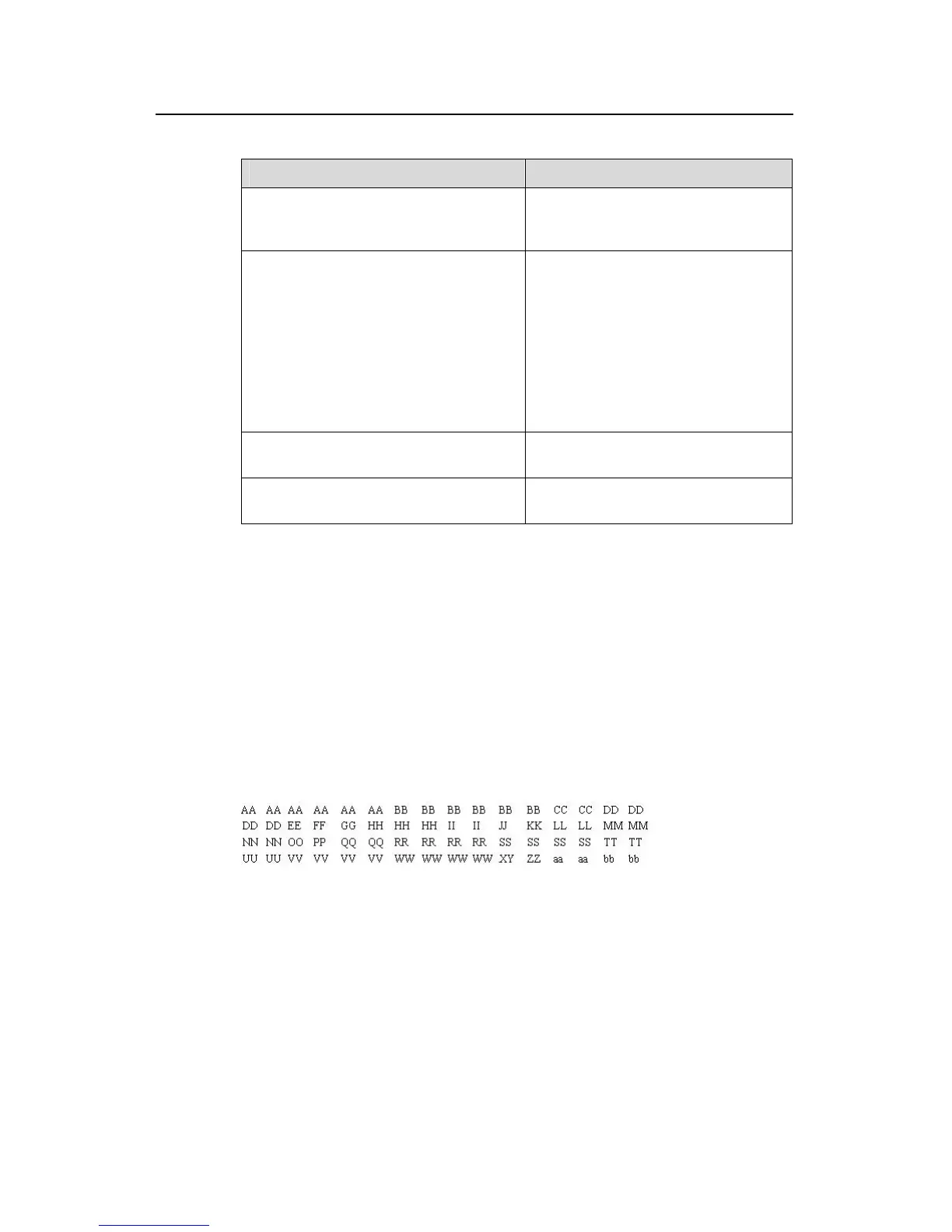
The user-defined ACL matches any bytes in the first 64 bytes of the Layer-2 data frame
with the character string defined by the user and then processes them accordingly. To
correctly use the user-defined ACL, you are required to understand the Layer-2 data
frame structure. The figure below shows the first 64 bytes of the Layer-2 data frame.
(Every letter represents a hexadecimal number and every two letters are one byte.)
Figure 1-1 The first 64 bytes of data frame
The table below lists the meaning and offset of each letter.
 Loading...


