5-26
5-4 Regenerative Resistor Setting
- SV Series User’s Manual -
COMMON PARAMETER SETTING
handled by built-in regenerative resistor of the servo amplifier, please connect an external regenerative resistor with a
corresponding capacity calculated through the above calculation.
In addition, when loss of the load system in Step 2 is unknown, please calculate again assuming that E
L
=0.
For operation period in continuous regenerative status, you should first add the following items to the above
calculation steps, then calculate the required capacity of regenerative resistor.
• Energy during operation period in continuous regenerative status : E
G
[J]
• Energy consumed by regenerative resistor : E
K
= E
S
- (E
L
+ E
M
+ E
C
) + E
G
• Required capacity of regenerative resistor : W
K
= E
K
/ (0.2 x T)
Where E
G
=(2π/60) x n
MG
x T
G
x t
G
T
G
: Torque of servo motor during operation period in continuous regenerative status [N·m]
n
MG
: Speed of servo motor during operation [min
-1
], same as above
t
G
: Operation time [s], same as above
• Please select an external regenerative resistor within the following range of sizes.
SV-075□2/100□2:40Ω or more
SV-150□2:20Ω or more
SV-200□2/300□2:12Ω or more
SV-500□2:8Ω or more
For the external regenerative resistors of below 20Ω, it is recommended to use the power type cement
resistors made by Iwaki Musen (RH type).
• If value of the regenerative resistor capacity is too large, then time for consuming the regenerative
energy will be longer. If the regenerative energy cannot be consumed completely during the operation
period, the "Regenerative overload" alarm (320) may occur. Be sure to use a regenerative resistor with
a smaller resistance value as much as possible.
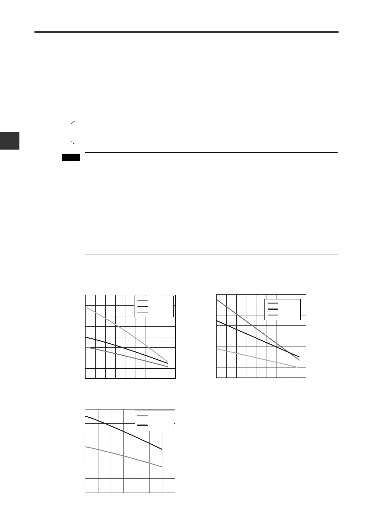
● Energy that can be absorbed by servo amplifier
The energy that can be absorbed by the capacitor in the servo amplifier is shown below.
• 200V type servo amplifier
• 100V type servo amplifier
50Wˉ200W
400W
750W
50W
-
200W
400W
750W, 1kW
Absorbable energy [J]
80
70
60
50
40
30
20
10
0
170 180 190 200 210 220 230 240 250 260
Input voltage [Vrms]
Absorbable energy [J]
Input voltage [Vrms]
170 180 190 200 210 220 230 240 250 260
0
20
40
60
80
100
120
140
160
5kW
2kW, 3kW
1.5kW
50W
-
200W
400W
Absorbable energy [J]
Input voltage [Vrms]
85 90 95 100 105 110 115 120
60
50
40
30
20
10
0
 Loading...