10-12
10-5 Acquisition of Absolute Position
- SV Series User’s Manual -
ABSOLUTE POSITION SYSTEM
■ Serial Communication Specifications
After "Absolute position data request (SEN)" signal is input, A-phase will becomes serial communication terminal. The
specifications of serial communication are as follows:
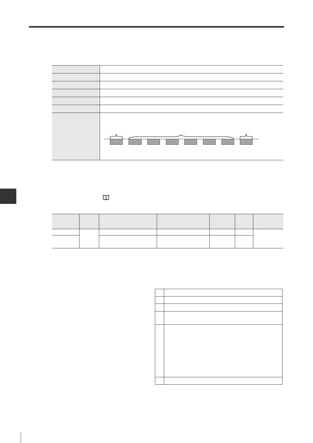
■ Default incremental pulse specification
Encoder position within one revolution will be output as the default number of incremental pulses.
Number of pulse outputs for one revolution is determined by "Encoder output pulse" (SYS_03) .
For output pulse train, see "5-2 Common Function Setting", Page 5-4.
Parameters required for setting are as follows.
■ Calculation of absolute position data
The absolute value of higher-level equipment is calculated with rotation value and default incremental pulses.
The following formula is used:
• Motor rotate direction: for CCW (SYS_05=0)
P
E
= (M x R) + P
O
P
M
= P
E
- P
S
• Motor rotate direction: for CW (SYS_05=1)
P
E
= (-M x R) + P
O
P
M
= P
E
- P
S
Data transfer mode
Demodulation sync
Baud rate
9600bps
Start bit
1 bit
Stop bit
1 bit
Parity bit
Even
Character code
ASCII 7 bit
Data format
Normal
Data:
-
32768 to+32767 (signed)
*For zero position rotation, data is "+00000_ or "
-
00000".
*Next data of -32768 is 32767, next data of 32767 is 32768.
Parameter
type
Category
Parameter name Setting range
Setting
unit
Default
Enable
timing
SYS_03
System
*Encoder output pulse 16 to 262144 PLS/Rev 2048
When power
ON again
SYS_05 *Motor rotate direction
0: CCW
1: CW
-0
P
E
Current value read from encoder
M Rotation value serial data
P
O
Default incremental pulse
R
Number of pulses in one rotation of encoder
(SYS_03 x magnification)
P
S
Absolute position data that may be read from the set point
(this value is stored and managed by higher-level equipment)
P
S
= M
S
x R + P
S
'
M
S
: Rotation value serial data that may be read from the set
point
P
S
' : Default incremental encoder that may be read from the
set point
P
M
Current value required in higher-level system
 Loading...