10-13
10-5 Acquisition of Absolute Position
ABSOLUTE POSITION SYSTEM
- SV Series User’s Manual -
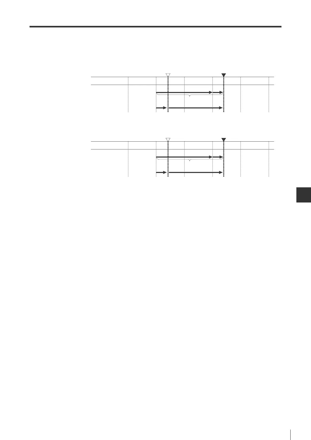
■ Coordinate diagram for absolute position data calculation
Absolute position data is calculated with the following coordinate diagram.
• Motor rotate direction: When CCW (SYS_05=0)
• Motor rotation direction: When CW (SYS_05=1)
Coordinate value is the coordinate value output by encoder for each rotation, so it is different from actual command unit
(encoder resolution). The higher-level equipment needs to convert pulse to command unit according to encoder pulse
and encoder resolution.
-
1
-
1
P
S
P
M
P
E
P
O
±0
Reference position (setting) Current position
+1
M x R
+2 +3
01234
Coordinate value
(Encoder pulse unit)
M value
+1
-
1
P
S
P
M
P
E
P
O
±0
Reference position (setting) Current position
+1
ˉM x R
+2 +3
0
-
1
-
2
-
3
-
4
Coordinate value
(Encoder pulse unit)
M value
 Loading...