3-6
INSTALLATION AND MAINTENANCE
3-1 Installation
- SV Series User’s Manual -
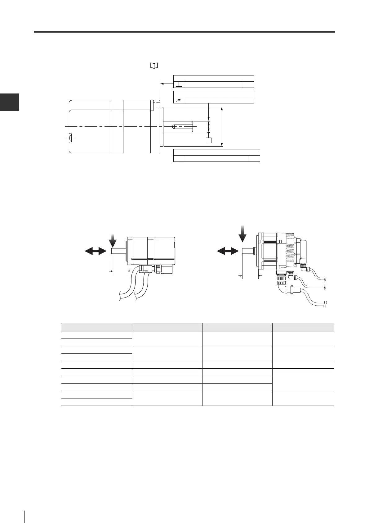
● Working precision
The instructions below must be followed for the precision of installing the output shaft of servo motor.
For the precision of each model, see "2-5 Dimensions", Page 2-17.
● Permissible load
The permissible radial load (load relative to the vertical direction of servo motor shaft) and axial load (relative to the
horizontal direction of servo motor shaft) applied on the shaft end of servo motor is shown as follows.
■ Degree of protection
The degree of protection of servo motor is IP65. (except for the shaft connecting part)
50W to 750W : IP65
1kW to 5kW : IP67
Measures such as installing a cover must be taken when oil drop are easy to enter the shaft connecting part.
Vertical degree for output shaft to flange surface
0.04 A
Allowable jump for output shaft end
0.02
Coaxial degree for output shaft to match outer diameter
0.04 AƼ
A
Model
Permissible radial load (N)
Permissible axial load (N) L (mm)
SV-005
78 54 20
SV-010
SV-020
245 74 25
SV-040
SV-075 392 147 35
SV-100A 490 98
58SV-150A 686 343
SV-200A 980 392
SV-300A
1470 490 79
SV-500A
Radial load
Axial load
L
Radial load
xial load
L
● SV-005/010/020/
040/075
● SV-100A/150A/200A/
300A/500A
 Loading...