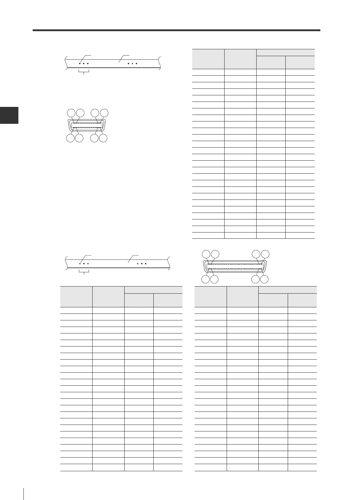
Pin No. Cable color
Point
Pin No. Cable color
Point
Color
Number of
marks
Color
Number of
marks
1 Orange Red 1 26 White Black 3
2 Orange Black 1 27 Yellow Red 3
3GrayRed1 28YellowBlack3
4 Gray Black 1 29 Pink Red 3
5 White Red 1 30 Pink Black 3
6 White Black 1 31 Orange Red 4
7 Yellow Red 1 32 Orange Black 4
8 Yellow Black 1 33 Gray Red 4
9PinkRed1 34GrayBlack4
10 Pink Black 1 35 White Red 4
11 Orange Red 2 36 White Black 4
12 Orange Black 2 37 Yellow Red 4
13 Gray Red 2 38 Yellow Black 4
14 Gray Black 2 39 Pink Red 4
15 White Red 2 40 Pink Black 4
16 White Black 2 41 Orange Red Continuous
17 Yellow Red 2 42 Orange Black Continuous
18 Yellow Black 2 43 Gray Red Continuous
19 Pink Red 2 44 Gray Black Continuous
20 Pink Black 2 45 White Red Continuous
21 Orange Red 3 46 White Black Continuous
22 Orange Black 3 47 Yellow Red Continuous
23 Gray Red 3 48 Yellow Black Continuous
24 Gray Black 3 49 Pink Red Continuous
25 White Red 3 50 Pink Black Continuous
 Loading...