4-196 Options Service Manual
4024-XXX
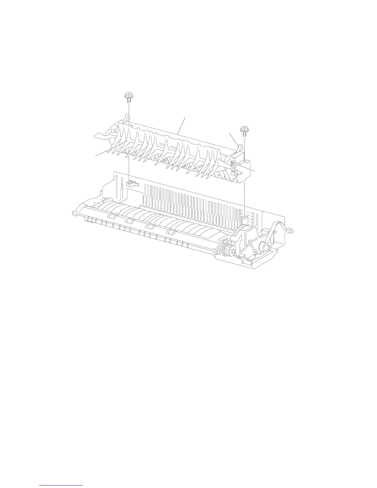
4. Remove the upper guide assembly (A).
Note: The exit 2 access handle (B) may become detached.
5. Remove the spring (C) connecting the exit 2 diverter gate (D) to the upper guide assembly (A).
6. Gently flex the mounting points securing the exit 2 diverter gate (D) to the upper guide assembly (A).
7. Remove the exit 2 diverter gate (D)
Note: After reinstalling the upper guide assembly (A), ensure the exit 2 access handle (B) operates freely.