UM10462 All information provided in this document is subject to legal disclaimers. © NXP B.V. 2016. All rights reserved.
User manual Rev. 5.5 — 21 December 2016 461 of 523
NXP Semiconductors
UM10462
Chapter 24: LPC11U3x/2x/1x Appendix ARM Cortex-M0
24.4.4 Memory access instructions
Table 427 shows the memory access instructions:
24.4.4.1 ADR
Generates a PC-relative address.
24.4.4.1.1 Syntax
ADR Rd, label
where:
Rd is the destination register.
label is a PC-relative expression. See Section 24–24.4.3.5
.
24.4.4.1.2 Operation
ADR generates an address by adding an immediate value to the PC, and writes the result
to the destination register.
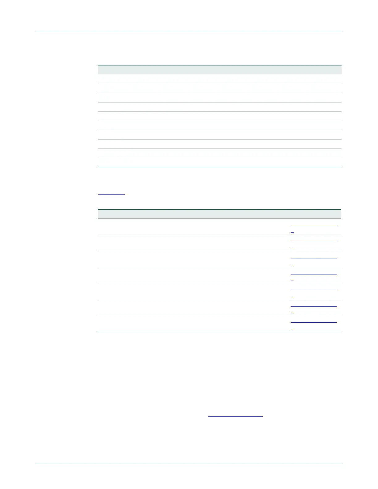
PL N = 0 Positive or zero
VS V = 1 Overflow
VC V = 0 No overflow
HI C = 1 and Z = 0 Higher, unsigned
LS C = 0 or Z = 1 Lower or same, unsigned
GE N = V Greater than or equal, signed
LT N = V Less than, signed
GT Z = 0 and N = V Greater than, signed
LE Z = 1 and N = V Less than or equal, signed
AL Can have any value Always. This is the default when no suffix is specified.
Table 426. Condition code suffixes
Suffix Flags Meaning
Table 427. Access instructions
Mnemonic Brief description See
LDR{type} Load Register using register offset Section 24–24.4.4.
3
LDR Load Register from PC-relative address Section 24–24.4.4.
4
POP Pop registers from stack Section 24–24.4.4.
6
PUSH Push registers onto stack Section 24–24.4.4.
6
STM Store Multiple registers Section 24–24.4.4.
5
STR{type} Store Register using immediate offset Section 24–24.4.4.
2
STR{type} Store Register using register offset Section 24–24.4.4.
3

 Loading...


