Image Adjustment
SM 4-257 D0CA/D0C9/D0C8/D0CB
&
Adjustment
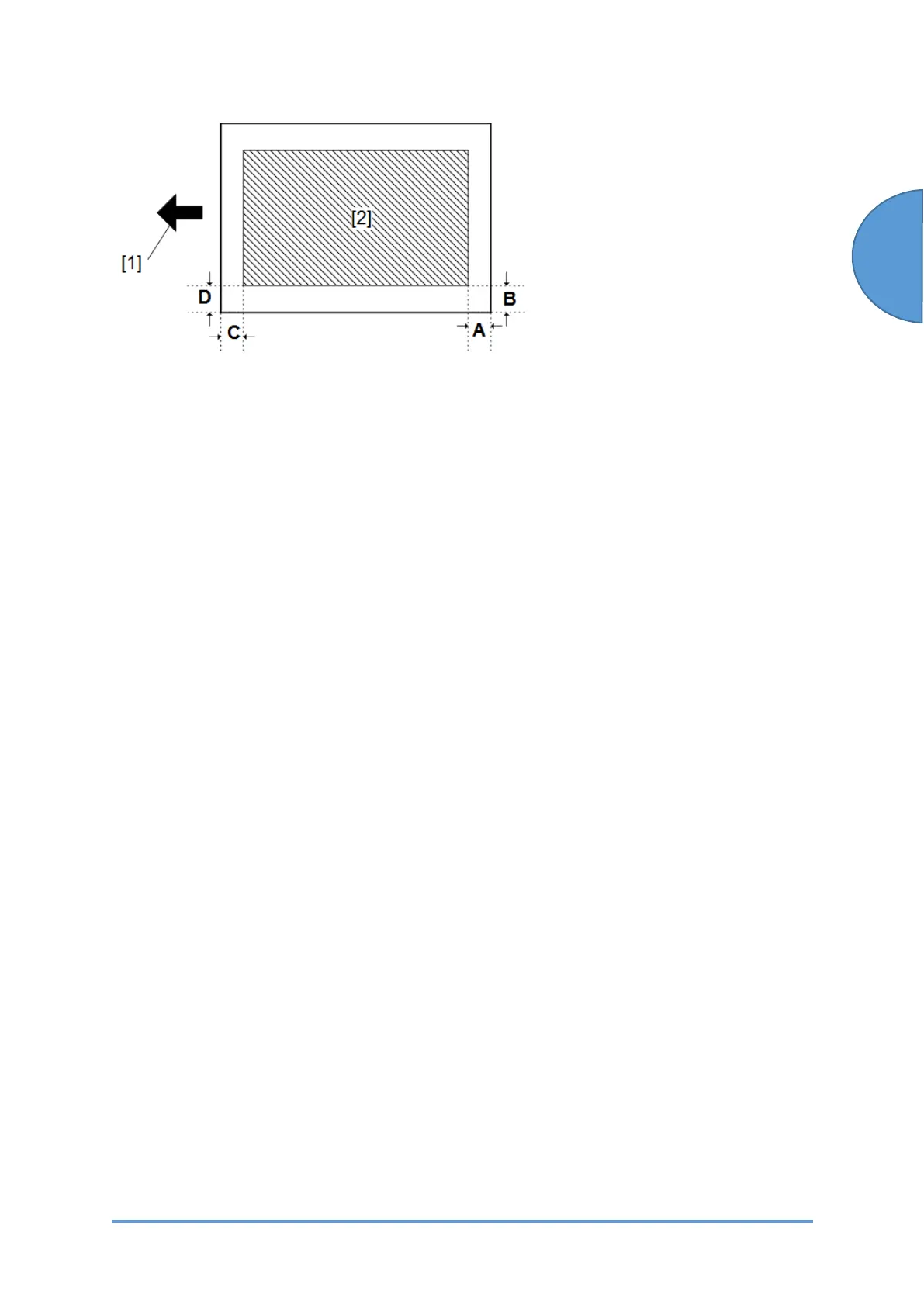
[1]: Feed direction, [2]: Image area
1. Enter the SP mode.
2. Print out the test pattern (14: 1-dot trimming pattern) with SP2-109-003.
3. Check the erase margin A and B. Adjust them with SP2-103-001 to -004 if necessary.
• Leading edge: 0.0 to 9.9 mm (default: 4.2 mm)
• Side-to-side: 0.0 to 9.9 mm (default: 2.0 mm)
• Trailing edge: 0.0 to 9.9 mm (default: 4.2 mm)
4.20.6 COLOR REGISTRATION
Line Position Adjustment
The automatic line position adjustment usually is done for a specified condition to get the best
color prints.
Do the following if color registration shifts:
• Do "Auto Color Registration" as follows to do the forced line position adjustment.
1. First do SP2-111-003.
2. Then do SP2-111-001.
To check if SP2-111-001 was successful, watch the screen during the process. A message
is displayed at the end. Also, you can check the result with SP2-194-010 to -012.
• You should also do the line position adjustment at these times:
• After you transport or move the machine (you should do the forced line position
adjustment if you install the machine at the user location) if the machine is
pre-installed at the workshop and moved to the user location,
• When you remove or replace the motors, clutches, and/or gears related to the
drum/development/transfer sections
• When you remove or replace the image transfer belt, image transfer belt unit or laser
optical housing unit
 Loading...