Service Program Mode
D0CA/D0C9/D0C8/D0CB 3-6 SM Appendices
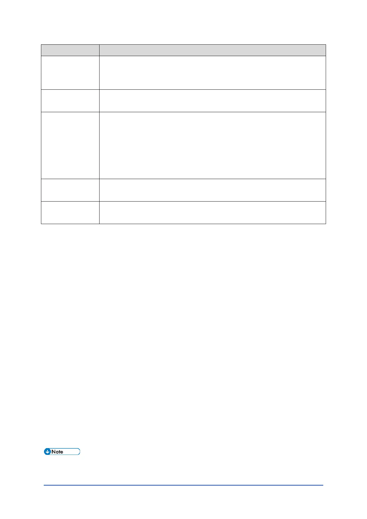
Item Description
Paper Type N: Normal paper
MTH: Middle thick paper
TH: Thick paper
Paper Feed
Station
P: Paper tray
B: Bypass table
Color Mode
[Color]
[K]: Black in B&W mode
[Y], [M], or [C]: Yellow, Magenta, or Cyan in Full Color mode
[YMC]: Only for Yellow, Magenta, and Cyan
[FC]: Full Color mode
[FC, K], [FC, Y], [FC, M], or [FC, C]: Black, Yellow, Magenta, or Cyan in full
color mode
Print Mode S: Simplex
D: Duplex
Process Speed L: Low speed (89 mm/s)
M: Middle speed (178 mm/s)
Others
The following symbols are used in the SP mode tables.
FA: Factory setting
(Data may be adjusted from the default setting at the factory. Refer to the factory setting sheets
enclosed. You can find it under the jammed paper removal decal.)
DFU: Design/Factory Use only
Do not touch these SP modes in the field.
A sharp (#) to the right hand side of the mode number column means that the main switch must
be turned off and on to effect the setting change.
An asterisk (*) to the right hand side of the mode number column means that this mode is
stored in the NVRAM and EEPROM. If you do a RAM clear, this SP mode will be reset to the
default value. "ENG" and "CTL" show which NVRAM contains the data.
• ENG: EEPROM on the BiCU board
• CTL: NVRAM on the controller board (PCB24)
The settings of each SP mode are explained in the right-hand column of the SP table in the
following way.
[Adjustable range / Default setting / Step] Alphanumeric
• If "Alphanumeric" is written to the right of the bracket as shown above, the setting of
the SP mode shows on the screen using alphanumeric characters instead of only

 Loading...
