Process Control and MUSIC
SM 7-71 D0CA/D0C9/D0C8/D0CB
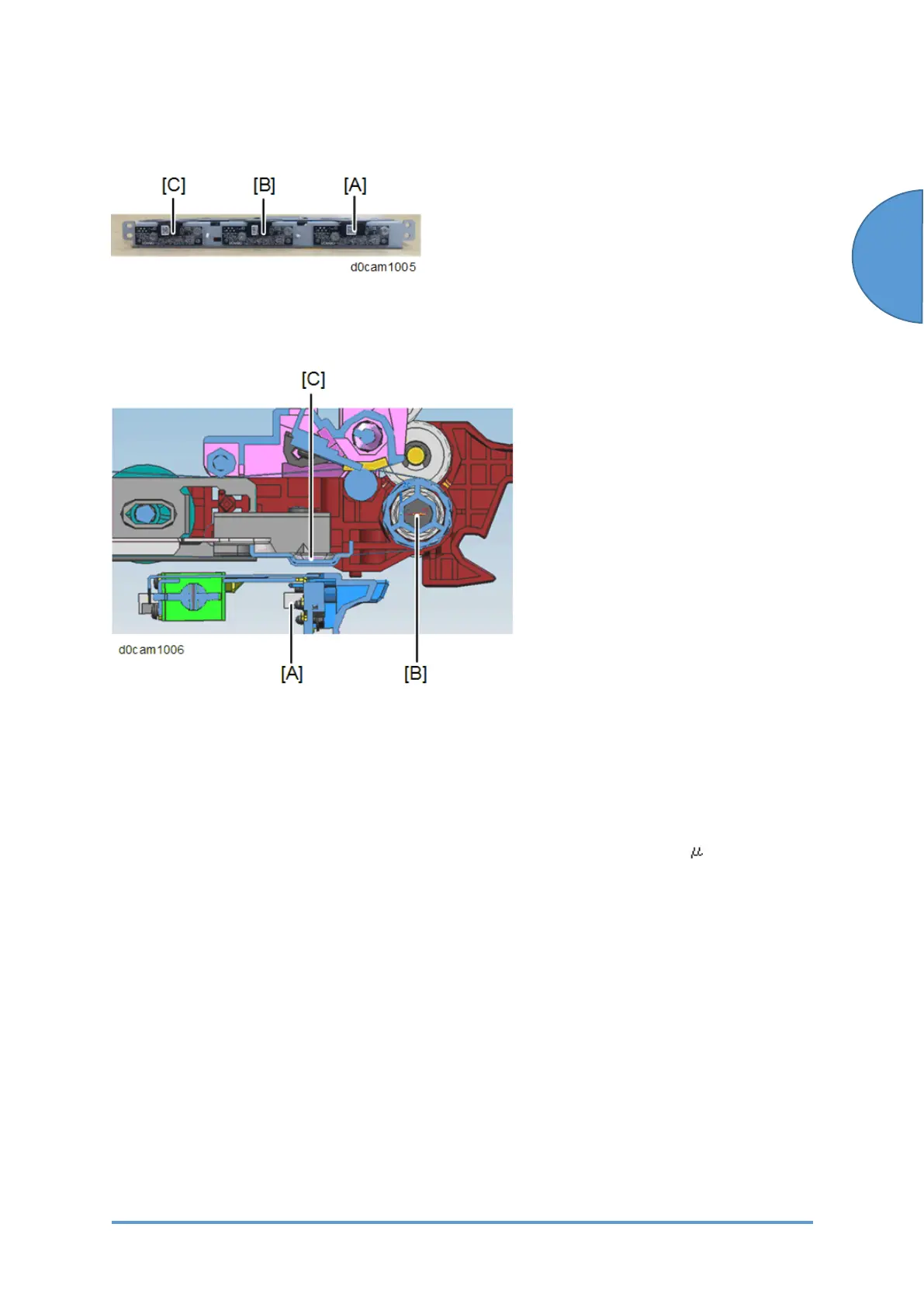
ID sensor (S27-S29)
The ID sensor (S27-S29) has 3 sensors laid out on 1 bracket. The ID sensor (center) (S28) [B]
acts as an ID sensor and a MUSIC sensor. The ID sensor (front) (S27) [A] and ID sensor (rear)
(S29) [C] are used only for MUSIC.
The ID sensors (S27-S29) [A] are installed at the upstream side of the paper transfer roller [B]
and detect image density at the plate [C]. This layout allows the machine to detect a pattern
faster and to help reduce waiting time.
TD Sensor (S14-S17)
In this model, a non-contact toner density (TD) sensor, which we also call a mu ( ) sensor, is
used for toner density control.
The TD sensor (S14-S17) is attached on the lower side of the development unit. Unlike a HST
sensor, the board of the TD sensor is exposed. So there is a cover around the sensor to protect
it and to maintain a good contact between the sensor and development unit.
The TD (S14-S17) sensor measures the permeability of the developer without contacting it,
from the outside of the case, and converts the measured value to the toner density.
According to the toner density measured by this sensor, the proper amount of toner is supplied
to the developer.
A counter corresponding to the frequency is used as the unit of TD sensor output. Thus, unlike a
HST sensor which directly detects Vt, the TD sensor output is converted into Vt for toner supply
control.
In the TD sensor (S14-S17), there is an ID chip (PCB3-PCB6) storing the machine identification
 Loading...