Reference ID: Name used to represent this 1PPS input reference in the
Reference Priority table; see "Configuring Input Reference Priorities" on
page205 for more information on reference priorities.
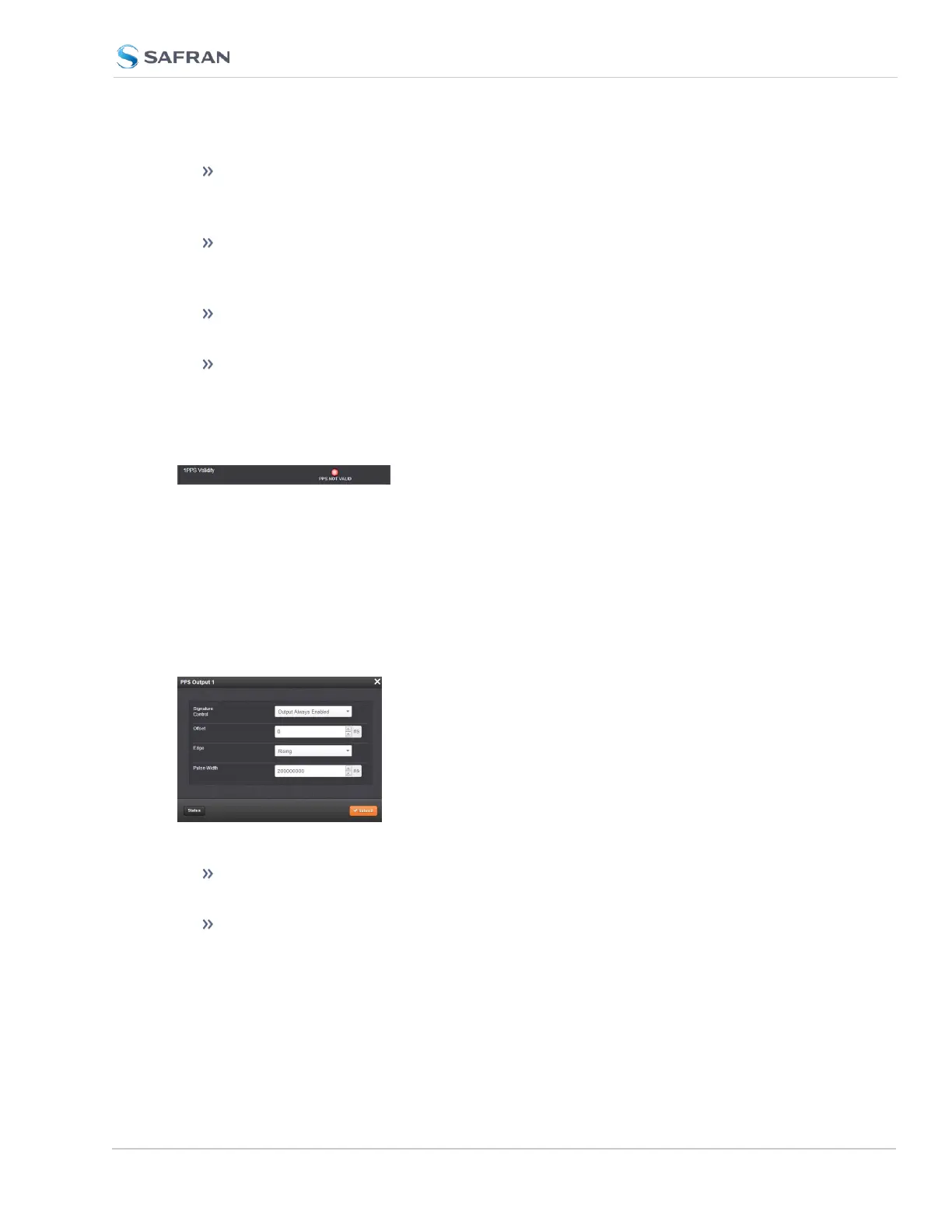
1PPS Validity: Indicates “OK” (green) if the 1PPS input signal is present and
valid. Indicates “Not Valid” (orange) if the 1PPS input signal is either not
present or is not considered valid.
Reference Mode: Displays how the reference mode operates in determ-
ining its validity.
Frequency: Displays (in Hertz) the configured frequency of the input fre-
quency signal.
The 1PPS Input signal is analyzed and an absence of the signal triggers a “Not
Valid” indication.
1PPS Output: Edit Window
To configure the settings of the 1PPS output, go to its Edit window. For instruc-
tions, see: "Configuring Option Card Inputs/Outputs" on page364.
The Web UI list entries for these cards are: 1PPS/Frequency BNC and 1PPS/Fre-
quency RS-485.
The connector number is: J3 (BNC card); J1 (RS-485 card).
The Edit window allows the configuration of the following settings:
Signature Control: Used to control when the 1PPS output signal will be
present. See "Signature Control" on page183 for more information.
Offset: Used to account for 1PPS cable delays or other latencies in the 1PPS
output. The Offset value is entered and displayed in nanoseconds (ns). The
available Offset range is -500 to +500ms.
SecureSync 2400 User Manual 401
APPENDIX