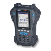
How to Set Up Your GX Series Microlog
System Settings
Autorange – The input range is determined using autoranging with fast data
collection. This setting limits input stage gain to 0 dB and attempts to get the
peak between 1% and 70% of hardware input range. Note that there is a
higher potential for sensor settling error. The input range is automatically
increased and the data retaken if clipping occurs. This ensures that the final
input range used will never be too low for the signal being measured.
Maximum – No autoranging is performed. The input range is fixed to the
hardware’s maximum input range. This setting provides faster display
updates.
Sensor Units – (Not applicable to the ROUTE module.) No autoranging is
performed. In modules other than the ROUTE module, the input range is set
based on module’s sensor type and sensitivity. The module’s input range
setting defaults to the middle input range option in module’s Setup menu. You
may alter the setting using the module’s Setup menu. The input range is
automatically increased and the data retaken if clipping occurs. This ensures
that the final input range used will never be too low for the signal being
measured.
Speed Measurement – Inactive, RPM, or Hz. (Not applicable to the ROUTE module.)
Determines if the measurement acquires and displays the shaft rotational speed as
measured by a connected tacho, and the speed units of measurement.
Inactive – The device will not acquire a shaft speed measurement for most
measurement types. For phase, orbit, order, balancing, and RUCD
measurements, the device can still acquire a shaft speed measurement if a
trigger input is present. The measurement displays in RPM.
RPM – The device acquires the shaft speed and displays it in RPM.
Hz – The device acquires the shaft speed and displays it in Hz.
Both RPM and Hz settings display additional Numerator
/
D
emominator fields that allow you multiply the tacho speed by
the numerator / denominator ratio - useful for gearboxes.
settings
s (eg Accel,
Triggered points (eg, RPM,
Phase, Orders, Time Sync
averaging)
Speed Measurement = Inactive
Trigger = Automatic
Measurements can be taken
without any trigger signal.
No option to measure speed.
Trigger signal is required for data
to be taken.
Trigger level is automatically
calculated by device.
Speed value will be shown in RPM
Speed Measurement = Inactive
Trigger = User
Measurements can be taken
without any trigger signal.
No option to measure speed.
Trigger signal is required for data
to be taken.
Trigger level needs to be manually
set by user.
Speed value will be shown in RPM
SKF Microlog - GX Series 2 - 3
User Manual

 Loading...