The Analyzer Module
How to Perform Multi-Channel Measurements
Phase readings do not shift by ninety degrees when integrating
between acceleration, velocity, and displacement. Phase
measurements are intended to be used in comparison to
diagnostic charts.
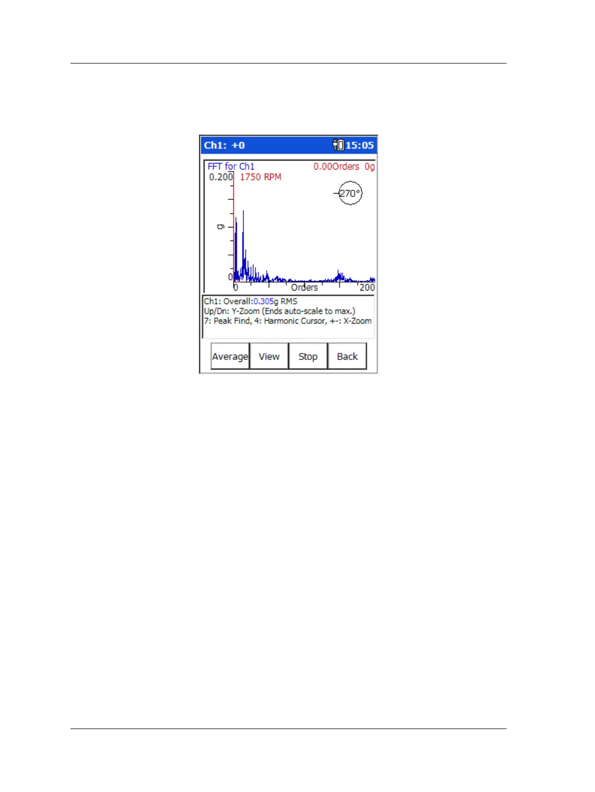
Figure 4 - 12.
An Example Spectrum & Phase Display.
Special Considerations When Taking Multi-Channel Measurements
Consider the following when connecting sensors for multi-channel analysis:
• For a single channel display connect the sensor to CH1.
• For a 2 channel measurement connect sensors to CH1 and CH2.
• For a 3 channel measurement display when using a tri-axial sensor, connect the
sensor cable to CH1.
• For a 3 channel measurement when using separate sensors, connect a single
sensor to CH1 (displays as the top trace), connect the CMAC 5079 cable (sold
separately) to CH2; connect the sensor for channel 2 to connector A - and the
sensor for channel 3 to connector B.
• For a 4 channel measurement, connect a CMAC 5079 cable to CH1 and CH2. The
CMAC 5079 connected to CH1 should have the sensor for channel 1 attached to
connector A and channel 4 attached to connector B. The CMAC 5079 cable
connected to CH2 should have the sensor for channel 2 attached to connector A
and the sensor for channel 3 attached to connector B.
4 - 20 SKF Microlog - GX Series
User Manual

 Loading...


