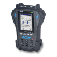
Data Recorder Module
How to Perform a Data Recorder Measurement
Recorder Measurement Setup Fields
Enter appropriate setup information in the following fields:
Input – Choose from:
CH1
CH1 & Tacho
CH1 & CH2
CH1 & CH2 & Tacho
CH1 & CH2 & CH3
CH1 & CH2 & CH3 & TACHO
Specify the input channel(s) for the Recorder measurement. Note that your selection
affects the Freq Range field’s maximum frequency setting and the recording’s
maximum recording time.
CH1 – 20 KHz maximum Freq Range
CH1 & CH2 – 10 KHz maximum Freq Range for each channel
CH1 & Tacho – 10 KHz maximum Freq Range for each channel
CH1 & CH2 & Tacho – 7.5 KHz maximum Freq Range for each channel
Sensor – Select the appropriate preconfigured sensor from the setup screen’s context
sensitive sensor list. Note that the specified sensor type determines available options
and engineering units for subsequent setup fields. Also note that in Reduced view setup
screens, the Sensor Units, Sensitivity, and ICP Supply parameters only display if the
Variable sensor is selected.
The Variable sensor option allows you to configure settings for a
sensor that is not on the sensor list.
Sensor Units – (Not editable if a preconfigured sensor is selected in the Sensor field.)
When the Variable sensor is selected, select the measurement units to use for the type
of sensor being used. Options include g, in/s, mil, V, psi, lbf, A, and mil.
Sensitivity – (Not editable if a preconfigured sensor is selected in the Sensor field.)
When the Variable sensor is selected, use the alphanumeric keypad to enter transducer
sensitivity in millivolts (mV) per Engineering Unit (EU).
ICP Power – (On or Off), (Not editable if a preconfigured sensor is selected in the
Sensor field.) When the Variable sensor is selected, select to turn ICP power Off or On
for the sensor.
Input Range - Specify the expected maximum amplitude range value for CH1. Note
that the Input Range setting determines the operation of some of the following fields.
Freq Range (Fmax)– From the drop down list, select the FFT upper full-scale frequency
in Hz, up to 20 KHz for CH1 inputs or up to 15 KHz for CH1 & CH2 and CH1 & Tacho
inputs or up to 10 KHz for CH1 & CH2 & Tacho. (Affects maximum recording time).
Save To – (Internal or Card) Specify the medium to record to, either the Microlog’s
Internal drive (not recommend due to large file size) or an inserted SD card
(recommended). In the screen’s information area, the maximum recording time is
determined by the measurement’s settings and the free space available on the specified
medium. (Affects maximum recording time).
SKF Microlog - GX Series 6 - 7
User Manual

 Loading...