Introduction to the SKF GX Series Microlog
Microlog System Connections
CH1, CH2, USB Device/Power/Trigger, and USB Host Connectors
Sensor input signals are connected through the CHannel 1 and CHannel 2 Fischer
connectors and the USB Host/CH 4 connector at the top of the Microlog.
With CH1 and CH2, no cable identification takes place to achieve the flexibility of
accepting signals from different sensors; including accelerometers, velocity and
displacement sensors, process inputs, etc. Therefore, the GX Series Microlog proceeds
to take data when the measurement is started, even though there may not be a sensor
or cable attached.
CH1 – Provides input capabilities for CH1, CH2, CH3, and CH4 signal input
channels.
CH2 – Provides input capabilities for CH2 and CH3 signal input channel.
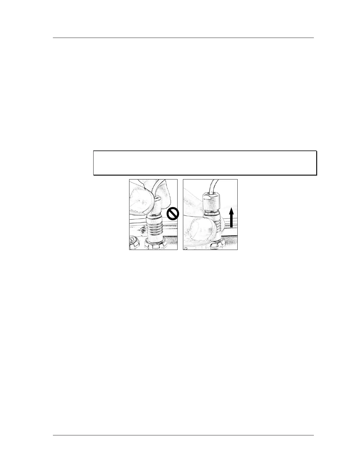
Important - Microlog connectors use a locking mechanism for secure connections.
To disconnect cables from the Microlog’s connectors, pull gently on the lower
portion of the connector as illustrated below.
Figure 1 - 11.
Wrong and Correct Way to Disconnect Microlog Cables.
USB Host/CH 4/Headphone –Provides USB keyboard support, input
capabilities for a CH4 signal input channel, and headphone support.
Headphone use requires accessory cable CMAC 5078.
In future firmware versions, the USB Host / Channel 4 connector
will connect additional USB peripherals (e.g., printer and mouse).
USB Device/Power/Trigger – To charge your Microlog’s batteries, connect the
supplied Microlog Power Supply to the unit’s Power connector. When power is
not being supplied to the unit, this connector is available for Trigger input.
Optionally, using the supplied USB / power splitter cable, you can supply power
to the unit at the same time you are performing USB communications.
The maximum measurement range is ± 24 V while the minimum full-scale range
voltage available is ± 10 mV (peak). Inputs are protected against higher voltage
transients, however, sustained over-voltage input levels must be avoided.
Voltage can be DC or AC coupled, while a Route ICP – As Database setting is available
for direct connection of integrated circuit piezoelectric transducers requiring 24 V dc /
2.4 mA (set in the Configuration screen), based on each POINT’s Enable ICP setting in
@ptitude Analyst POINT Properties.
SKF Microlog - GX Series 1 - 23
User Manual

 Loading...


