Spindle Test Module
Spindle Tests Overview
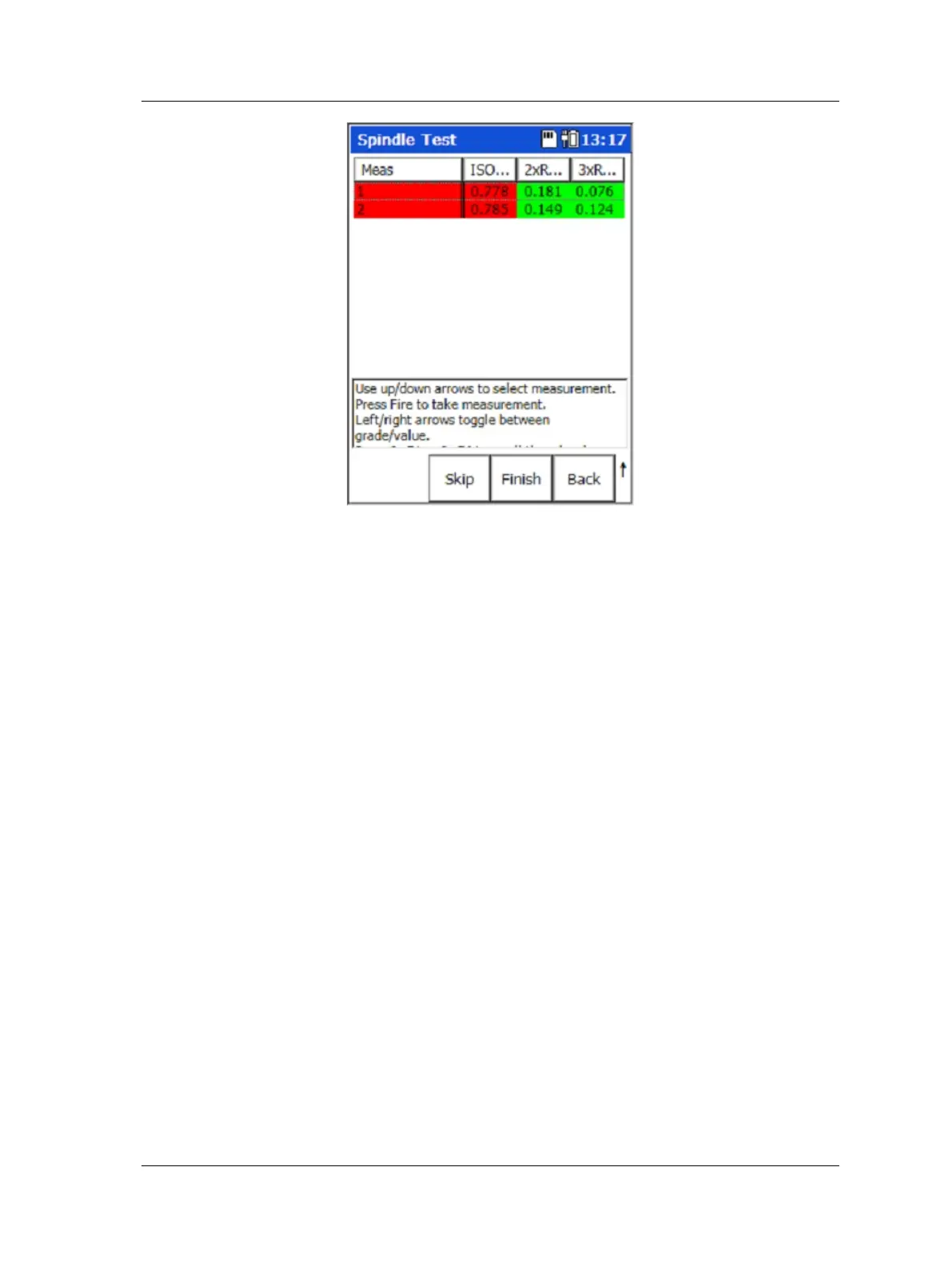
Figure 10 – 10.
Preset Vibration Measurements.
• Determine vibration values and evaluate against SKF vibration acceptance
standard.
Bearing Condition test overview
To perform a bearing condition test:
• Connect the sensor to the Microlog’s input marked “CH 1.”
• Install a balanced “master-tool” in the spindle nose.
• Run the spindle slowly to work temperature by step-wise increase in speed until
maximum speed is reached.
• Power the Microlog on.
• From the main menu, use the arrow buttons to highlight the RUCD icon and press
an Enter button. This is to determine any resonance frequencies. After
determining resonance frequency, select the Microlog’s Spindle module, and then
select the module’s Resonant Frequency test and enter the resonance frequency.
• Re-start spindle and increase the speed to approximately 80% of maximum speed
(or typical operating speed). Be sure to avoid any resonance domains.
• In the Bearing Condition test setup screen, enter the speed range for the spindle.
SKF Microlog - GX Series 10 - 9
User Manual

 Loading...


