Virtex-6 FPGA GTX Transceivers User Guide www.xilinx.com 211
UG366 (v2.5) January 17, 2011
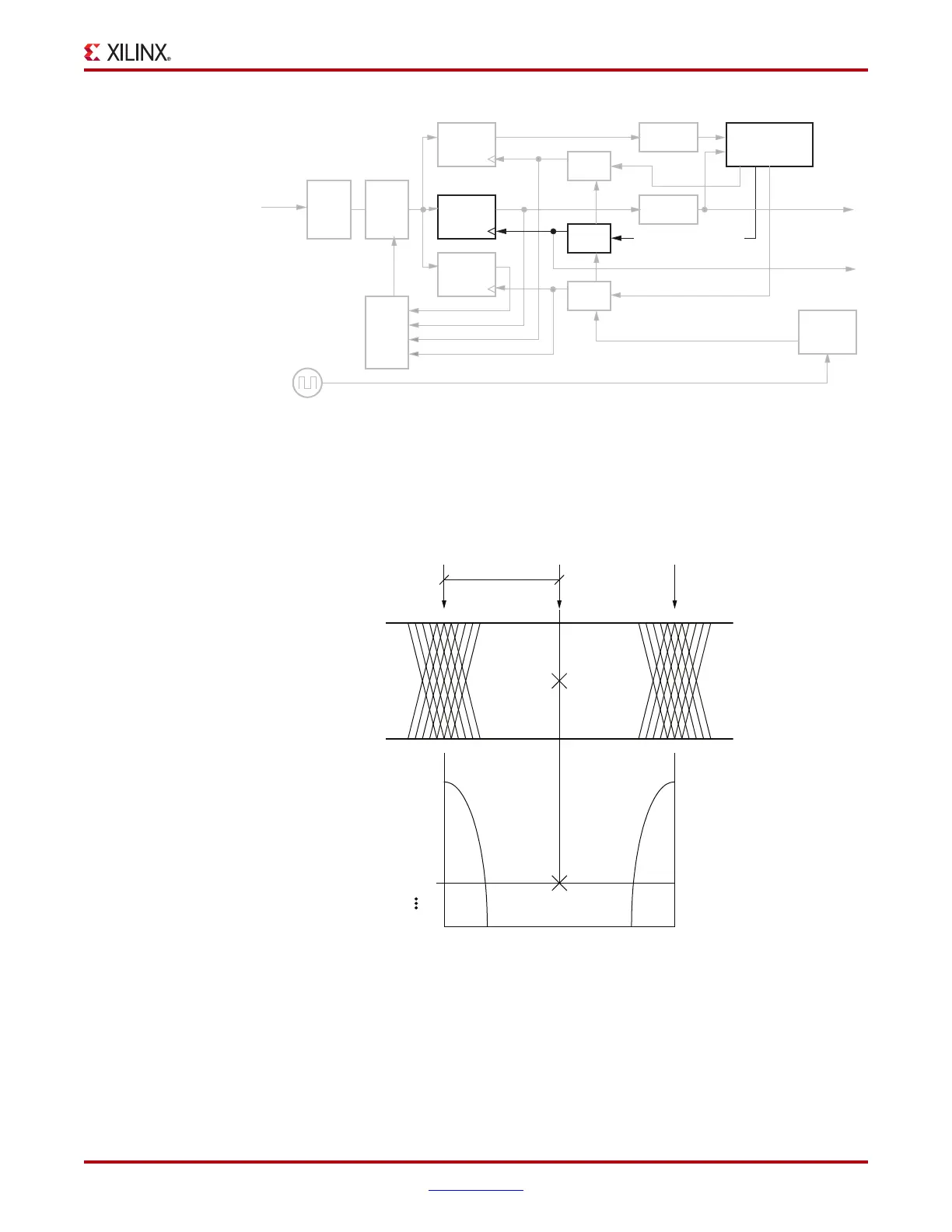
RX Margin Analysis
As illustrated in Figure 4-17, when the data sampling phase approaches the edge transition
region, user logic observes a corresponding increased in bit error rate on the received user
data.
This scan mode provides only the physical mechanism to offset the data sampling position.
It does not provide the actual scanning and bit error rate monitoring functionalities. These
functionalities need to be implemented in either FPGA user logic or user software. This
mode is only recommended for diagnostic purposes because the received user data is
corrupted due to the non-optimal sampling position.
X-Ref Target - Figure 4-16
Figure 4-16: Horizontal Eye Margin Scan Detail
X-Ref Target - Figure 4-17
Figure 4-17: Data Sampling Position to Bit Error Rate
UG366_c4_15_051509
Edge
Sampler
Demux
CDR FSM
Data
Sampler
Scan
Sampler
RXP/N
RXEQ
DFE
DFE
FSM
Local
REFCLK
PI (E)
PI (D)
PI (S)
RX
PLL
R XDATA
RXRECCLK
Demux
RX_EYE_OFFSET
UG366_c4_16_051509
Internal Eye Opening
BER
E
0
D
0
E
1
RX_EYE_OFFSET
1e
-6
1e
-8
1e
-10
1e
-12

 Loading...

