244 www.xilinx.com Virtex-6 FPGA GTX Transceivers User Guide
UG366 (v2.5) January 17, 2011
Chapter 4: Receiver
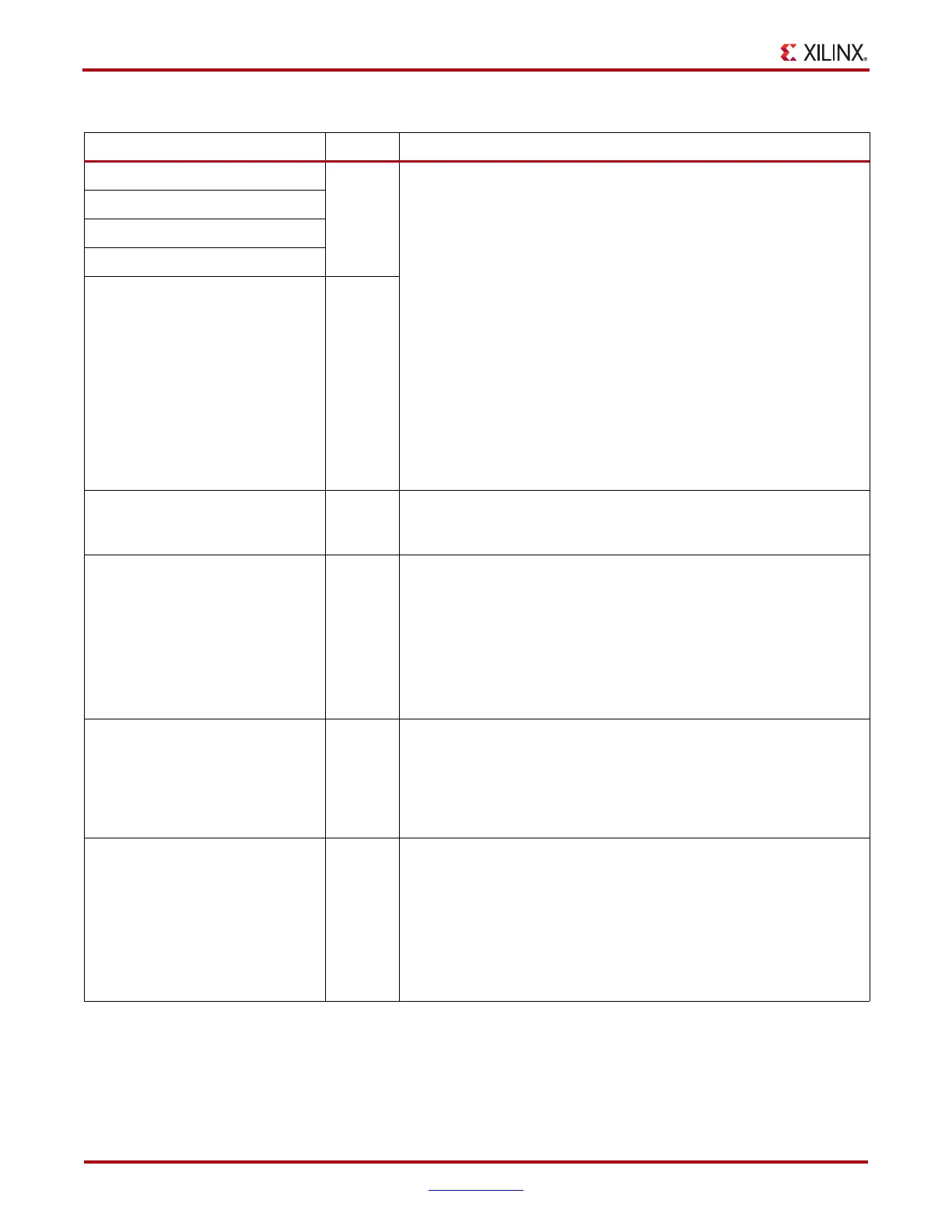
CLK_COR_SEQ_2_1 10-bit
Binary
The CLK_COR_SEQ_2 attributes are used in conjunction with
CLK_COR_SEQ_2_ENABLE to define the second clock correction
sequence. This second sequence is used as an alternate sequence for
clock correction when CLK_COR_SEQ_2_USE is TRUE: if either
sequence 1 or sequence 2 arrives, clock correction is performed.
The sequence is made up of four subsequences. Each subsequence is
10 bits long. The rules for setting the subsequences depend on
RX_DATA_WIDTH and RX_DECODE_SEQ_MATCH. See Setting
Clock Correction Sequences, page 245 to learn how to set clock
correction subsequences.
Not all subsequences need to be used. CLK_COR_DET_LEN
determines how much of the sequence is used for a match. If
CLK_COR_DET_LEN = 1, only CLK_COR_SEQ_2_1 is used.
CLK_COR_SEQ_2_ENABLE can be used to make parts of the sequence
don't care. If CLK_COR_SEQ_2_ENABLE[k] is 0, CLK_COR_SEQ_2_k
is a don't care byte subsequence and is always considered to be a
match.
CLK_COR_SEQ_2_2
CLK_COR_SEQ_2_3
CLK_COR_SEQ_2_4
CLK_COR_SEQ_2_ENABLE 4-bit
Binary
CLK_COR_SEQ_2_USE Boolean Determines if the second clock correction sequence is to be used. When
set to TRUE, the second clock correction sequence also triggers clock
correction.
CLK_CORRECT_USE Boolean Enables clock correction.
TRUE: Clock correction enabled
FALSE: Clock correction disabled. In this case, set:
CLK_COR_SEQ_1_1 = 10'b0100000000,
CLK_COR_SEQ_2_1 = 10'b0100000000,
CLK_COR_SEQ_1_ENABLE = 4'b1111
CLK_COR_SEQ_2_ENABLE = 4'b1111
RX_DATA_WIDTH Integer Sets the receiver external data width:
8/10: 1-byte interface
16/20: 2-byte interface
32/40: 4-byte interface
If 8B10B is used, this attribute must be a multiple of 10.
RX_DECODE_SEQ_MATCH Boolean Determines whether sequences are matched against the input to the
8B/10B decoder or the output. Used for the clock correction circuit and
the channel bonding circuit.
TRUE: Sequences are matched against the output of the 8B/10B
decoder. K characters and disparity information is used. Bit
ordering of the 8B/10B output is used.
FALSE: Sequences are matched against non-encoded data. Bit
ordering is as for an non-encoded parallel interface.
Table 4-47: RX Clock Correction Attributes (Cont’d)
Attribute Type Description

 Loading...

