Virtex-6 FPGA GTX Transceivers User Guide www.xilinx.com 275
UG366 (v2.5) January 17, 2011
Pin Description and Design Guidelines
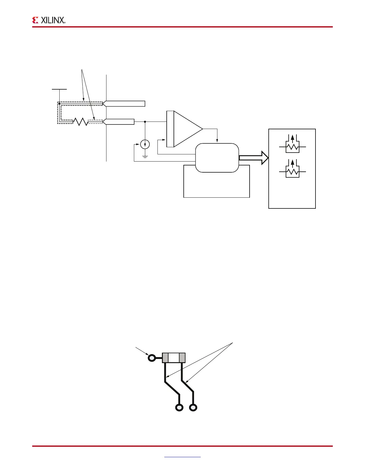
The MGTAVTTRCAL pin should be connected to the MGTAVTT supply and to a pin on the
100 precision external resistor. The other pin of the resistor is connected to the MGTRREF
pin. The resistor calibration circuit provides a controlled current load to the resistor that is
connected to the MGTRREF pin. It then senses the voltage drop across the external
calibration resistor and uses that value to adjust the internal resistor calibration setting.
The quality of the resistor calibration depends on the accuracy of the voltage measurement
at the MGTAVTTRCAL and MGTRREF pins. To eliminate errors due to the voltage drop
across the traces that lead from the resistor and to the FPGA pins, the trace from the
MGTAVTTRCAL pin to the resistor should have the same length and geometry as the trace
that connects the other pin of the resistor to the MGTRREF pin. Figure 5-3 shows a
recommended layout.
X-Ref Target - Figure 5-2
Figure 5-2: Termination Resistor Calibration Circuit
UG366_c5_02_051509
MGTRREF
Trace length from the resistor pins to the
FPGA pins MGTRREF and MGTVTTRCAL
must be equal in length and geometry
MGTAVTT
1.2V
Internal to FPGA
MGTAVTTRCAL
RREF
External 100Ω
Precision Resistor
Comparator
Internal Resistor
Network
“RCAL Master”
GTX Quad for
Resistor Calibration
Calibrated
Values
RX/TX
Termination
In Each
Quad
X-Ref Target - Figure 5-3
Figure 5-3: PCB Layout for the RCAL Resistor
UG366_c5_03_051509
100Ω
Trace length from the resistor pins to the
FPGA pins MGTRREF and MGTAVTTRCAL
must be equal in length
Connection
to AVTT
MGTAVTTRCAL
MGTRREF

 Loading...

