7.4.5 External Power Supply Installation
When connecting external power to the CR1000, remove the green POWER IN
connector from the CR1000 face. Insert the positive lead into the green
connector, then insert the negative lead. Re-seat the green connector into the
CR1000. The CR1000 is internally protected against reversed external-power
polarity. Should this occur, correct the wire connections.
7.5 Switched Voltage Output — Details
Related Topics:
• Switched Voltage Output — Specifications
• Switched Voltage Output — Overview
(p. 78)
• Switched Voltage Output — Details
(p. 103)
• PLC Control — Overview (p. 74)
• PLC Control — Details (p. 244)
• PLC Control Modules — Overview (p. 368)
• PLC Control Modules — Lists (p. 648)
• PLC Control — Instructions (p. 562)
The CR1000 wiring panel is a convenient power distribution device for powering
sensors and peripherals that require a 5 Vdc, or 12 Vdc source. It has two
continuous 12 Vdc terminals (12V), one program-controlled, switched, 12 Vdc
terminal (SW12), and one continuous 5 Vdc terminal (5V). SW12, 12V, and 5V
terminals limit current internally for protection against accidental short circuits.
Voltage on the 12V and SW12 terminals can vary widely and will fluctuate with
the dc supply used to power the CR1000, so be careful to match the datalogger
power supply to the requirements of the sensors. The 5V terminal is internally
regulated to within ±4%, which is good regulation as a power source, but typically
not adequate for bridge sensor excitation. Table Current Sourcing Limits
(p. 103)
lists the current limits of 12V and 5V terminals. Greatly reduced output voltages
on these terminals may occur if the current limits are exceeded. See the section
Terminals Configured for Control
(p. 368) for more information.
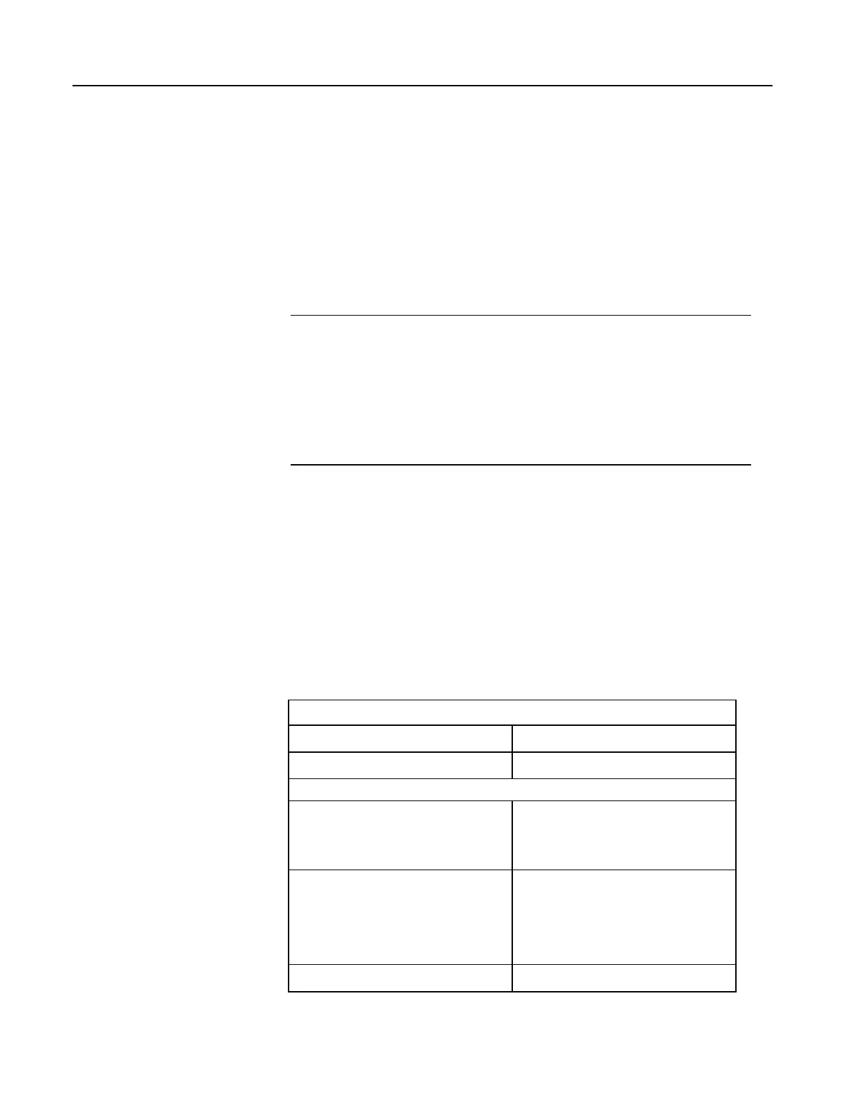
Table 5. Current Source and Sink Limits
Terminal
Limit
1
VX or EX (voltage excitation)
2
±25 mA maximum
SW-12
3
< 900 mA @ 20°C
< 630 mA @ 50°C
< 450 mA @ 70°C
12V + SW-12 (combined)
4
< 3.00 A @ 20°C
< 2.34 A @ 50°C
< 1.80 A @ 70°C
< 1.50 A @ 85°C
5V + CS I/O (combined)
5
< 200 mA
103

 Loading...

