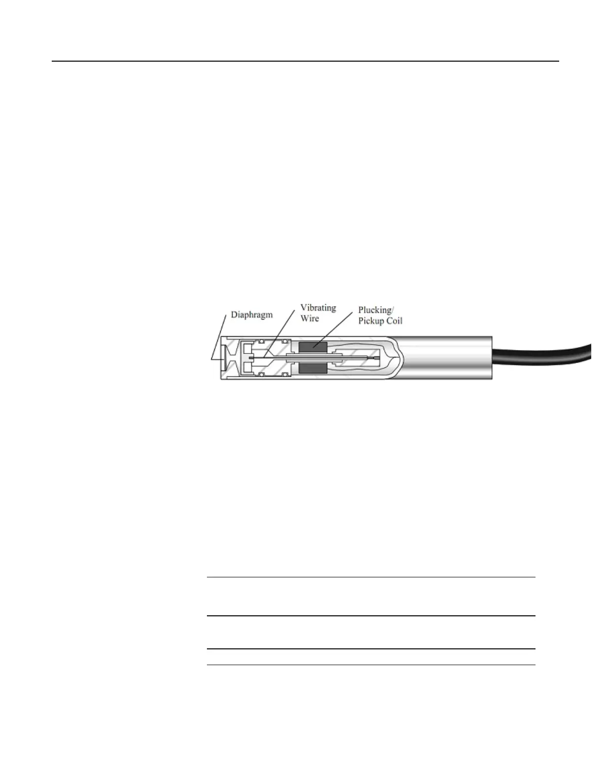
The figure Vibrating-Wire Sensor (p. 362) illustrates basic construction of a sensor.
To make a measurement, plucking and pickup coils are excited with a swept
frequency
(p. 530). The ideal behavior then is that all non-resonant frequencies
quickly decay, and the resonant frequency continues. As the resonant frequency
cuts the lines of flux in the pickup coil, the same frequency is induced on the
signal wires in the cable connecting the sensor to the CR1000 or interface.
Measuring the resonant frequency by means of period averaging is the classic
technique, but Campbell Scientific has developed static and dynamic spectral-
analysis techniques (VSPECT
(p. 532)t
m
) that produce superior noise rejection,
higher resolution, diagnostic data, and, in the case of dynamic VSPECT,
measurements up to 333.3 Hz.
A resistive-thermometer device (thermistor or RTD), which is included in most
vibrating-wire sensor housings, can be measured to compensate for temperature
errors in the measurement.
Figure 96. Vibrating-Wire Sensor
8.1.5.1 Time-Domain Measurement
Although obsolete in many applications, time-domain period-averaging vibrating-
wire measurements can be made on H L terminals. The VibratingWire()
instruction makes the measurement. Measurements can be made directly on these
terminals, but usually are made through a vibrating-wire interface that amplifies
and conditions the vibrating-wire signal and provides inputs for embedded
thermistors or RTDs. Interfaces of this type are no longer available from
Campbell Scientific.
For most applications, the advanced techniques of static and dynamic VSPECT
TM
measurements are preferred.
8.1.6 Reading Smart Sensors — Details
Related Topics:
• Reading Smart Sensors — Overview (p. 71)
• Reading Smart Sensors — Details
(p. 362)
8.1.6.1 RS-232 and TTL
Read More Serial Input / Output Instructions (p. 583) and Serial I/O (p. 245).
The CR1000 can receive and record most TTL (0 to 5 Vdc) and true RS-232 data
from devices such as smart sensors. See the table CR1000 Terminal Definitions
(p.
362

 Loading...

