FIGURE. Simplified Voltage Measurement Sequence -- 8 10 30
Figure 79. Simplified voltage measurement sequence
Voltage measurements are made using a successive approximation A-to-D (p. 507)
converter to achieve a resolution of 14 bits. Prior to the A-to-D, a high
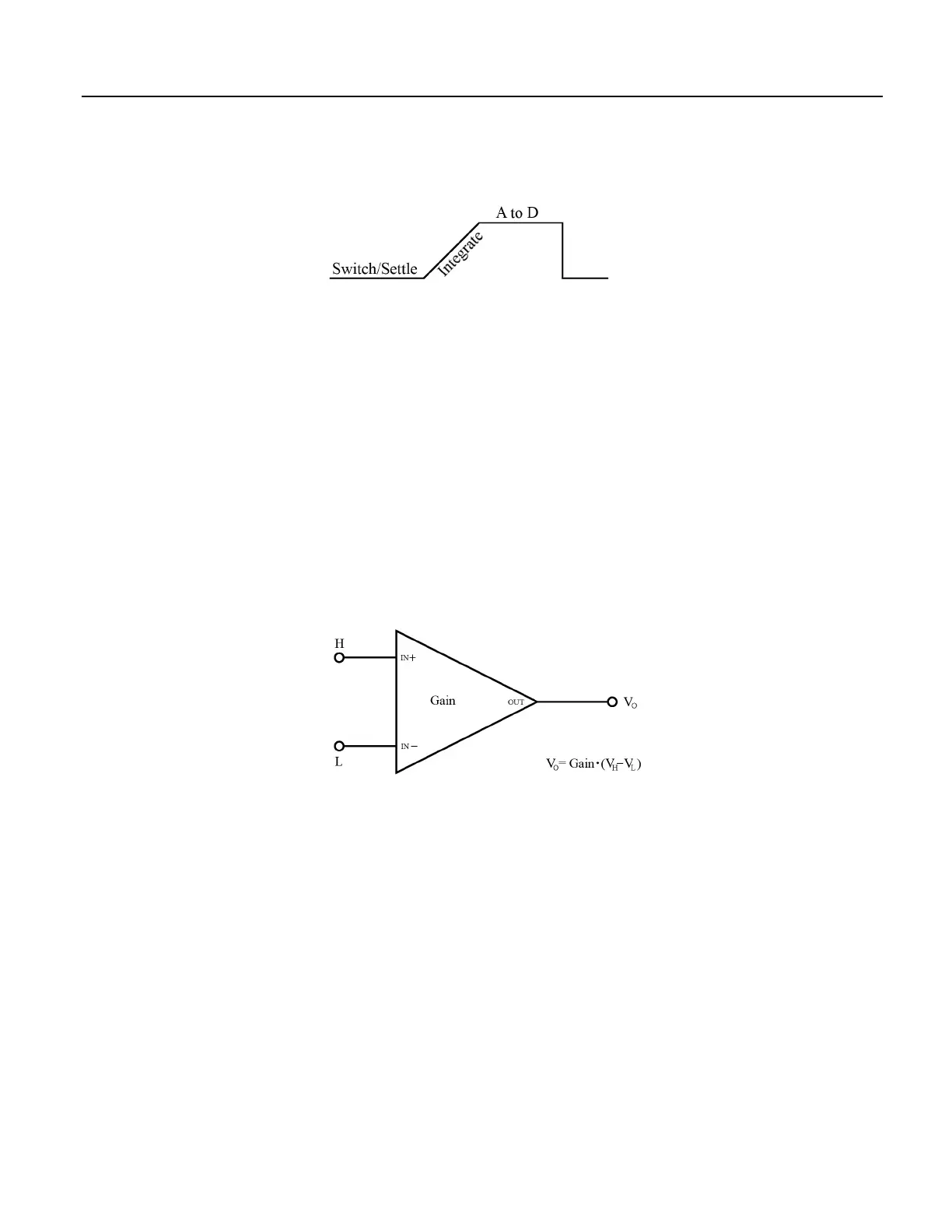
impedance programmable-gain instrumentation amplifier (PGIA) amplifies the
signal. See figure Programmable Gain Input Amplifier (PGIA)
(p. 306). The
CRBasic program controls amplifier gain and configuration — either single-ended
input or differential input. Internal multiplexers route individual terminals to the
PGIA.
Timing of measurement tasks is precisely controlled. The measurement schedule
is determined at compile time and loaded into memory.
Using two different voltage-measurement instructions with the same voltage
range takes about twice as long as using one instruction with two repetitions.
Parameters listed in table CRBasic Parameters Varying Measurement Sequence
and Timing
(p. 307) vary sequence and timing of voltage measurement instructions.
Figure 80. Programmable Gain Input Amplifier (PGIA)
A voltage measurement proceeds as follows:
1. Set PGIA gain for the voltage range selected with the CRBasic measurement
instruction parameter Range.
2. Turn on excitation to the level selected with ExmV.
3. Multiplex selected terminals (InChan) to the PGIA and delay for the entered
settling time (SettlingTime).
4. Integrate the signal (see section Measurement Integration
(p. 307) ) and perform
the A-to-D conversion.
5. Repeat for excitation reversal and input reversal as determined by parameters
RevEx and RevDiff.
6. Apply multitplier (Mult) and offset (Offset) to measured result.
306
 Loading...


