Section 4. System Quickstart
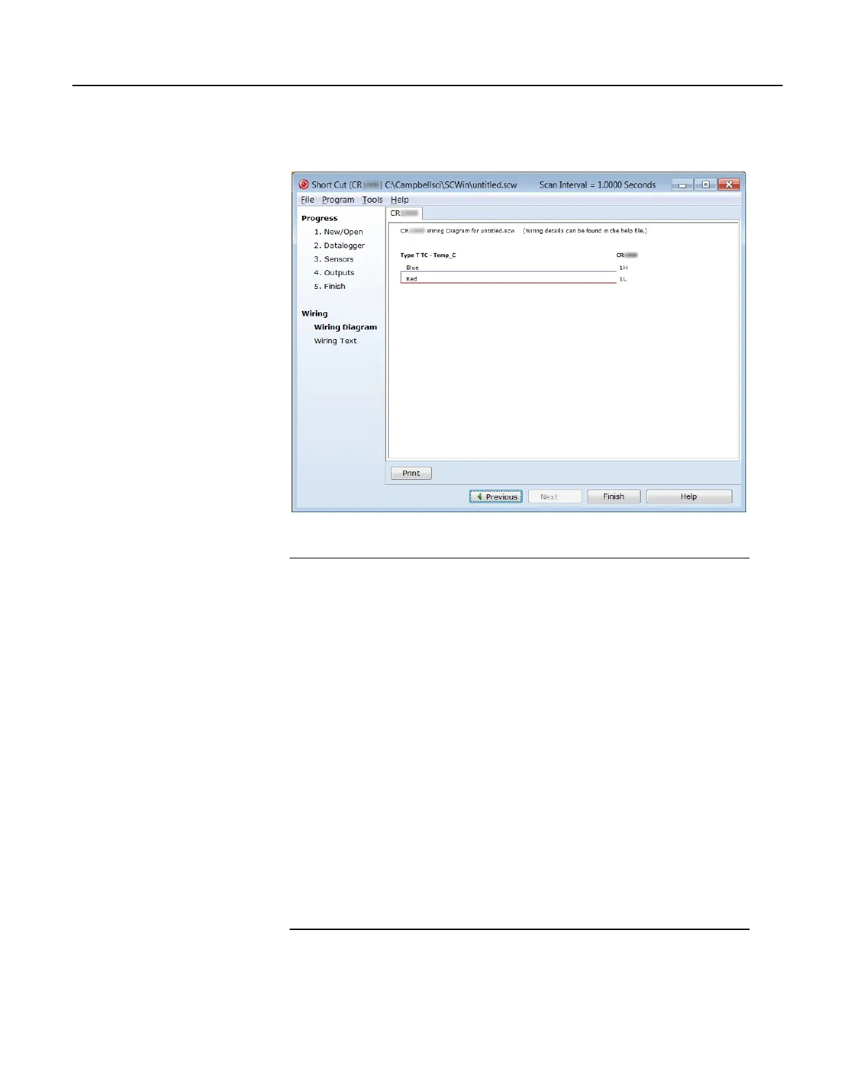
Figure 6. Short Cut Thermocouple Wiring
4.7.4.3 Procedure: (Short Cut Step 8)
Historical Note In the space-race era, measuring thermocouples in the field was
a complicated and cumbersome process incorporating a three-junction
thermocouple, a micro-voltmeter, a vacuum flask filled with an ice slurry, and a
thick reference book. One junction connected to the micro-voltmeter. Another sat
in the vacuum flask as a 0 °C reference. The third was inserted into the location of
the temperature of interest. When the microvolt measurement settled out, the
microvolt reading was recorded by hand. This value was then looked up on the
appropriate table in the reference book to determine the equivalent temperature.
Then along came Eric and Evan Campbell. Campbell Scientific designed the first
CR7 datalogger to make thermocouple measurements without the need for
vacuum flasks, reference books, or three junctions. Now, there's an idea!
Nowadays, a thermocouple need only consist of two wires of dissimilar metals,
such as copper and constantan, joined at one end. The joined end is the
measurement junction; the junction that is created when the two wires of
dissimilar metals are wired to CR1000 analog input terminals is the reference
junction.
When the two junctions are at different temperatures, a voltage proportional to the
temperature difference is induced in the wires. The thermocouple measurement
requires the reference-junction temperature to calculate the measurement-junction
temperature using proprietary algorithms in the CR1000 operating system.
52

 Loading...

