and water provide an alternate path for the excitation to return to CR1000 ground.
This example is modeled in the diagram Model of a Ground Loop with a Resistive
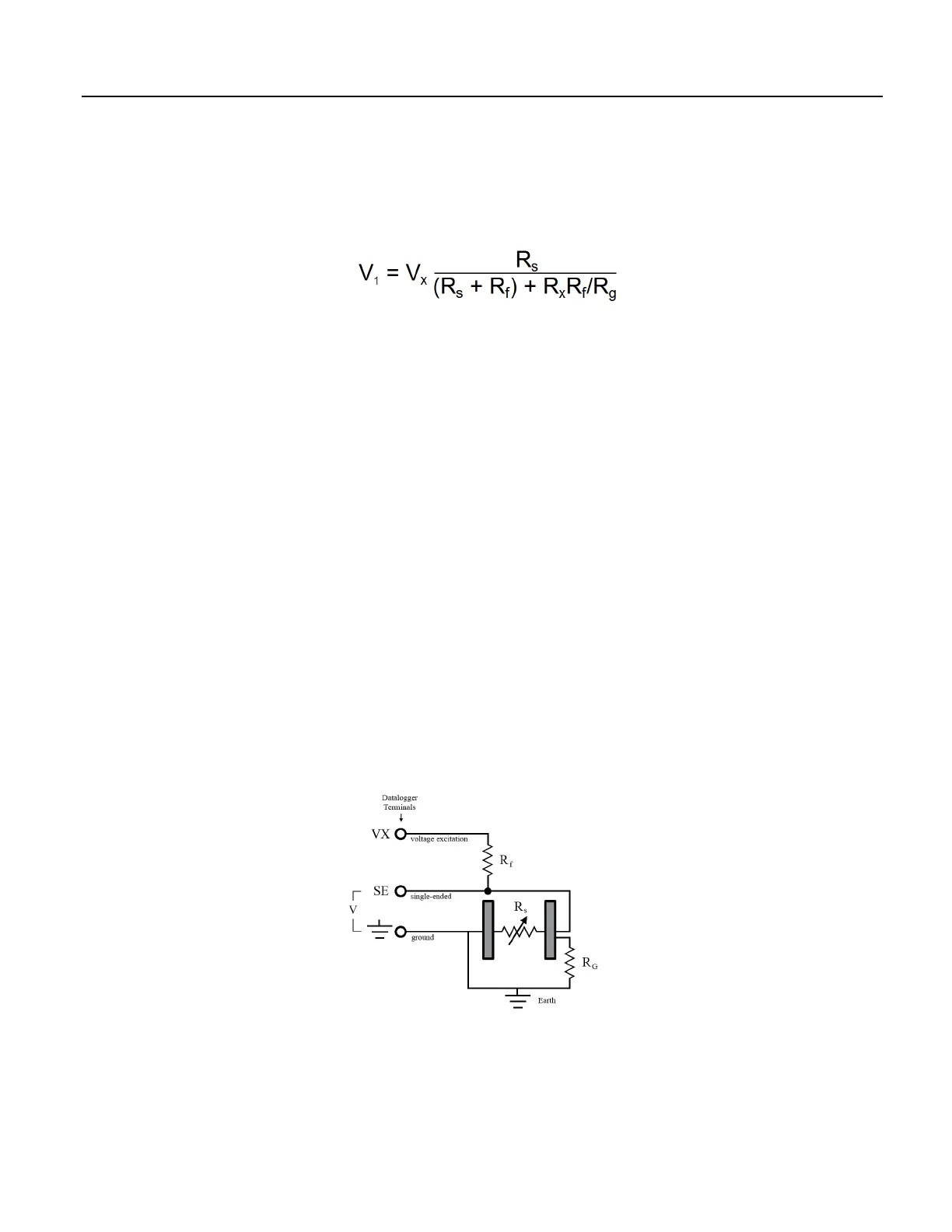
Sensor
(p. 110). With R
g
in the resistor network, the signal measured from the sensor
is described by the following equation:
where
V
x
is the excitation voltage
R
f
is a fixed resistor
R
s
is the sensor resistance
R
g
is the resistance between the excited electrode and CR1000 earth ground.
R
x
R
f
/R
g
is the source of error due to the ground loop. When R
g
is large, the error
is negligible. Note that the geometry of the electrodes has a great effect on the
magnitude of this error. The Delmhorst gypsum block used in the Campbell
Scientific 227 probe has two concentric cylindrical electrodes. The center
electrode is used for excitation; because it is encircled by the ground electrode, the
path for a ground loop through the soil is greatly reduced. Moisture blocks which
consist of two parallel plate electrodes are particularly susceptible to ground loop
problems. Similar considerations apply to the geometry of the electrodes in water
conductivity sensors.
The ground electrode of the conductivity or soil moisture probe and the CR1000
earth ground form a galvanic cell, with the water/soil solution acting as the
electrolyte. If current is allowed to flow, the resulting oxidation or reduction will
soon damage the electrode, just as if dc excitation was used to make the
measurement. Campbell Scientific resistive soil probes and conductivity probes
are built with series capacitors to block this dc current. In addition to preventing
sensor deterioration, the capacitors block any dc component from affecting the
measurement.
Figure 35. Model of a Ground Loop with a Resistive Sensor
110

 Loading...

