The CR1000 supports Modbus master and Modbus slave communications for
inclusion in Modbus SCADA networks. Modbus is a widely used SCADA
communication protocol that facilitates exchange of information and data between
computers / HMI software, instruments (RTUs) and Modbus-compatible sensors.
The CR1000 communicates with Modbus over RS-232, RS-485 (with a RS-232 to
RS-485 adapter), and TCP.
Modbus systems consist of a master (PC), RTU / PLC slaves, field instruments
(sensors), and the communication-network hardware. The communication port,
baud rate, data bits, stop bits, and parity are set in the Modbus driver of the master
and / or the slaves. The Modbus standard has two communication modes, RTU
and ASCII. However, CR1000s communicate in RTU mode exclusively.
Field instruments can be queried by the CR1000. Because Modbus has a set
command structure, programming the CR1000 to get data from field instruments
is much simpler than from serial sensors. Because Modbus uses a common bus
and addresses each node, field instruments are effectively multiplexed to a
CR1000 without additional hardware.
A CR1000 goes into sleep mode after 40 seconds of communication inactivity.
Once asleep, two packets are required before the CR1000 will respond. The first
packet awakens the CR1000; the second packet is received as data. CR1000s,
through DevConfig or the Status table (see the appendix Status Table and Settings
(p. 603)
) can be set to keep communication ports open and awake, but at higher
power usage.
8.6.2.1 Modbus Terminology
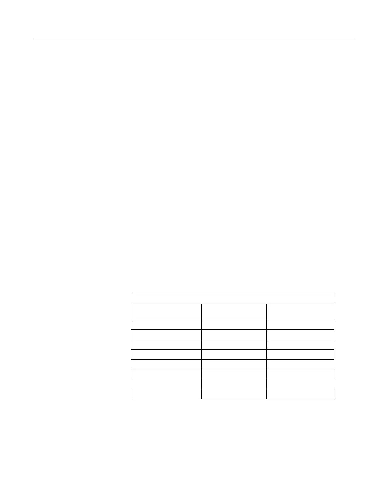
Table Modbus to Campbell Scientific Equivalents (p. 412) lists terminology
equivalents to aid in understanding how CR1000s fit into a SCADA system.
Table 106. Modbus to Campbell Scientific Equivalents
Modbus Domain Data Form Campbell Scientific
Domain
Coils Single bit Ports, flags, boolean variables
Digital registers 16 bit word Floating point variables
Input registers 16 bit word Floating point variables
Holding registers 16 bit word Floating point variables
RTU / PLC CR1000
Master Usually a computer
Slave Usually a CR1000
Field instrument Sensor
8.6.2.1.1 Glossary of Modbus Terms
Term. coils (00001 to 09999)
Originally, "coils" referred to relay coils. In CR1000s, coils are exclusively
terminals configured for control, software flags, or a Boolean-variable array.
412

 Loading...

