EasyManuals Logo

Campbell CR1000 User Manual

Campbell CR1000
678 pages
To Next Page IconTo Next Page
To Previous Page IconTo Previous Page
Page #227 background imageLoading...
Page #227 background image
Section 7. Installation
Figure 60. Strain-Gage Shunt Calibration Finish
7.9.12.6.4 FieldCalStrain() Quarter-Bridge Zero
Continuing from FieldCalStrain() Quarter-Bridge Shunt Example (p. 226), keep the
249 kΩ resistor in place to simulate a strain. Using the CR1000KD Keyboard
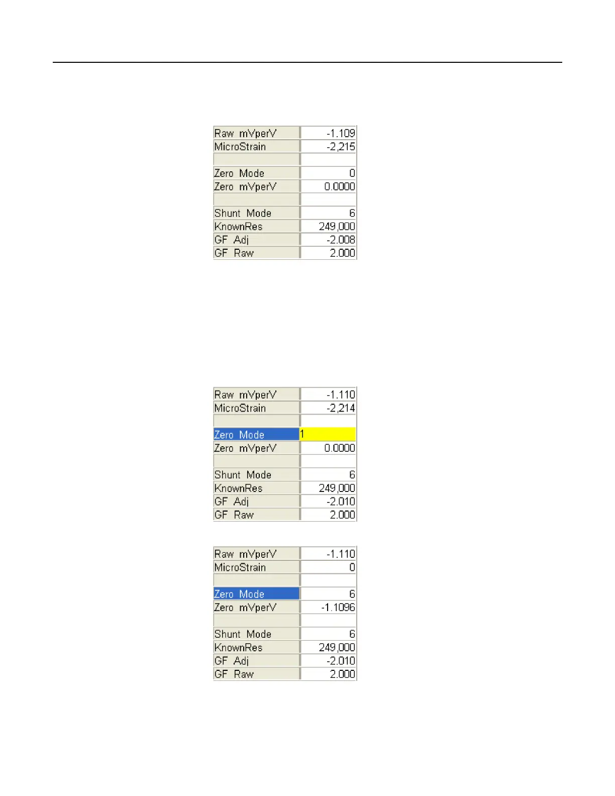
Display or software numeric monitor, change the value in variable Zero_Mode to
1 to start the zero calibration as shown in figure Zero Procedure Start
(p. 227).
When Zero_Mode increments to 6, zero calibration is complete as shown in
figure Zero Procedure Finish
(p. 227).
Figure 61. Zero Procedure Start
Figure 62. Zero Procedure Finish
227

Table of Contents

Questions and Answers:

Question and Answer IconNeed help?

Do you have a question about the Campbell CR1000 and is the answer not in the manual?

Campbell CR1000 Specifications

General IconGeneral
Power Requirements9.6 to 16 VDC
Data Logger Operating SystemCRBasic
Memory4 MB
Analog Inputs16 single-ended or 8 differential
Analog Input Resolution13 bits
Analog Input Range+/-2.5V
Digital I/O8
Pulse Counters2
Communication PortsRS-232
Operating Temperature-25°C to +50°C
Pulse Channels4

Related product manuals