The CR1000 measures analog voltage by integrating the input signal for a fixed
duration and then holding the integrated value during the successive
approximation analog-to-digital (A-to-D) conversion. The CR1000 can make and
store measurements from up to eight differential or 16 single-ended channels
configured from H/L terminals at the minimum scan interval of 10 ms (100 Hz)
using fast-measurement-programming techniques as discussed in Measurements:
Faster Analog Rates
(p. 229). The maximum conversion rate is 2000 per second (2
kHz) for measurements made on a one single-ended channel.
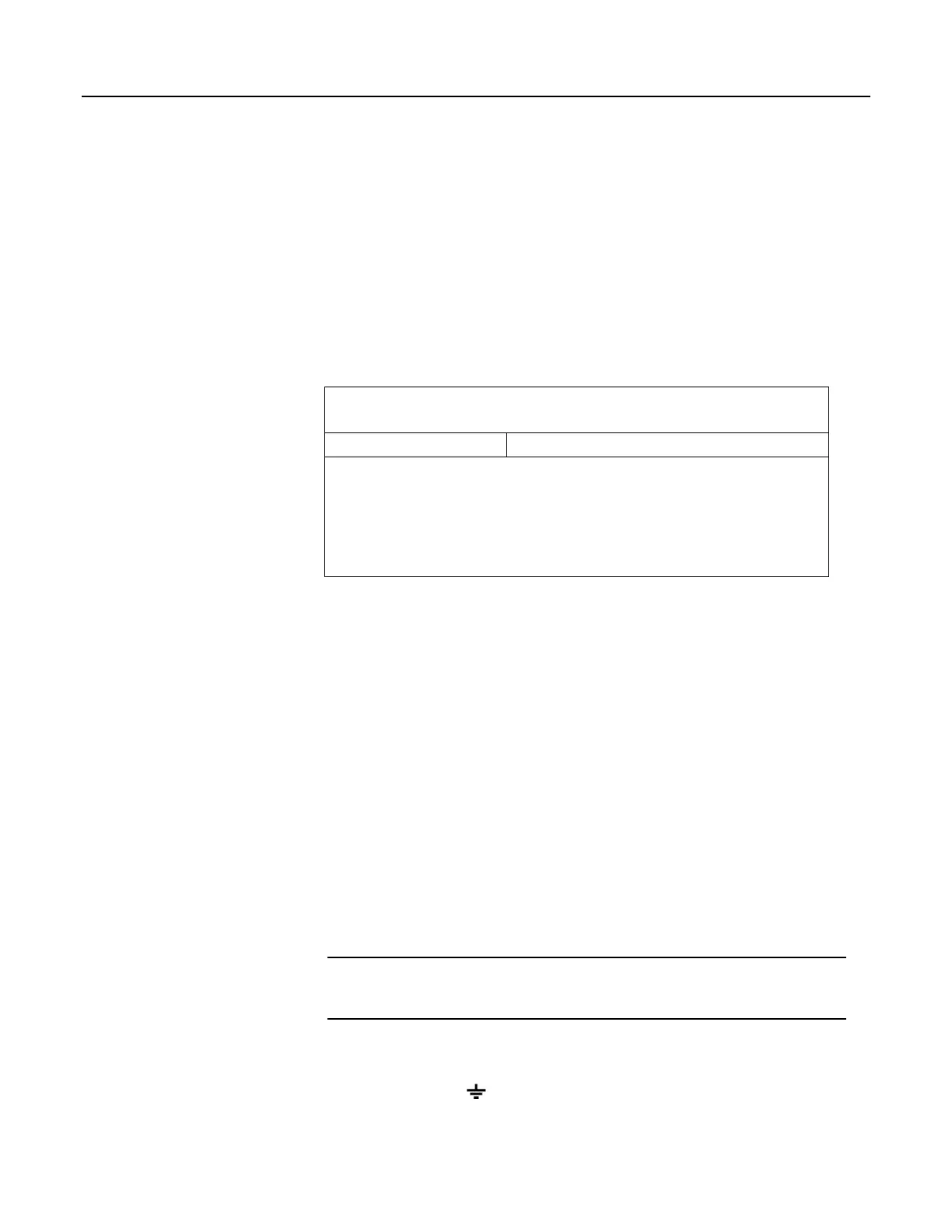
Table 54. CRBasic Parameters Varying Measurement Sequence and
Timing
CRBasic Parameter Description
MeasOfs
Correct ground offset on single-ended measurements.
SettlingTime
Sensor input settling time.
Integ Duration of input signal integration.
RevDiff
Reverse high and low differential inputs.
RevEx
Reverse polarity of excitation voltage.
Measurement Integration
Integrating the signal removes noise that creates error in the measurement. Slow
integration removes more noise than fast integration. Integration time can be
modified to reject 50 Hz and 60 Hz mains-power line noise.
Fast integration may be preferred at times to,
• minimize time skew between successive measurements.
• maximize throughput rate.
• maximize life of the CR1000 power supply.
• minimize polarization of polar sensors such as those for measuring
conductivity, soil moisture, or leaf wetness. Polarization may cause
measurement errors or sensor degradation.
improve accuracy of an LVDT measurement. The induced voltage in an LVDT
decays with time as current in the primary coil shifts from the inductor to the
series resistance; a long integration time may result in most of signal decaying
before the measurement is complete.
Single-Ended Measurements — Details
Related Topics:
• Single-Ended Measurements — Overview (p. 65)
• Single-Ended Measurements — Details
(p. 307)
With reference to the figure Programmable Gain Input Amplifier (PGIA) (p. 306),
during a single-ended measurement, the high signal (H) is routed to V+. The low
signal (L) is automatically connected internally to signal ground with the low
signal tied to ground (
) at the wiring panel. V+ corresponds to odd or even
307

 Loading...

