Appending the Range code with a C results in a 50 µs internal connection of the
V+ input of the PGIA to a large over-voltage. The V– input is connected to
ground. Upon disconnecting the inputs, the true input signal is allowed to settle
and the measurement is made normally. If the associated sensor is connected, the
signal voltage is measured. If the input is open (floating), the measurement will
over-range since the injected over-voltage will still be present on the input, with
NAN as the result.
Range codes and applicable over-voltage magnitudes are found in the table
Range-Code Option C Over-Voltages
(p. 322).
The C option may not work, or may not work well, in the following applications:
• If the input is not a truly open circuit, such as might occur on a wet cut cable
end, the open circuit may not be detected because the input capacitor
discharges through external leakage to ground to a normal voltage within the
settling time of the measurement. This problem is worse when a long settling
time is selected, as more time is given for the input capacitors to discharge to
a "normal" level.
• If the open circuit is at the end of a very long cable, the test pulse (300 mV)
may not charge the cable (with its high capacitance) up to a voltage that
generates NAN or a distinct error voltage. The cable may even act as an aerial
and inject noise which also might not read as an error voltage.
• The sensor may "object" to the test pulse being connected to its output, even
for 100 µs. There is little or no risk of damage, but the sensor output may be
caused to temporarily oscillate. Programming a longer settling time in the
CRBasic measurement instruction to allow oscillations to decay before the A-
to-D conversion may mitigate the problem.
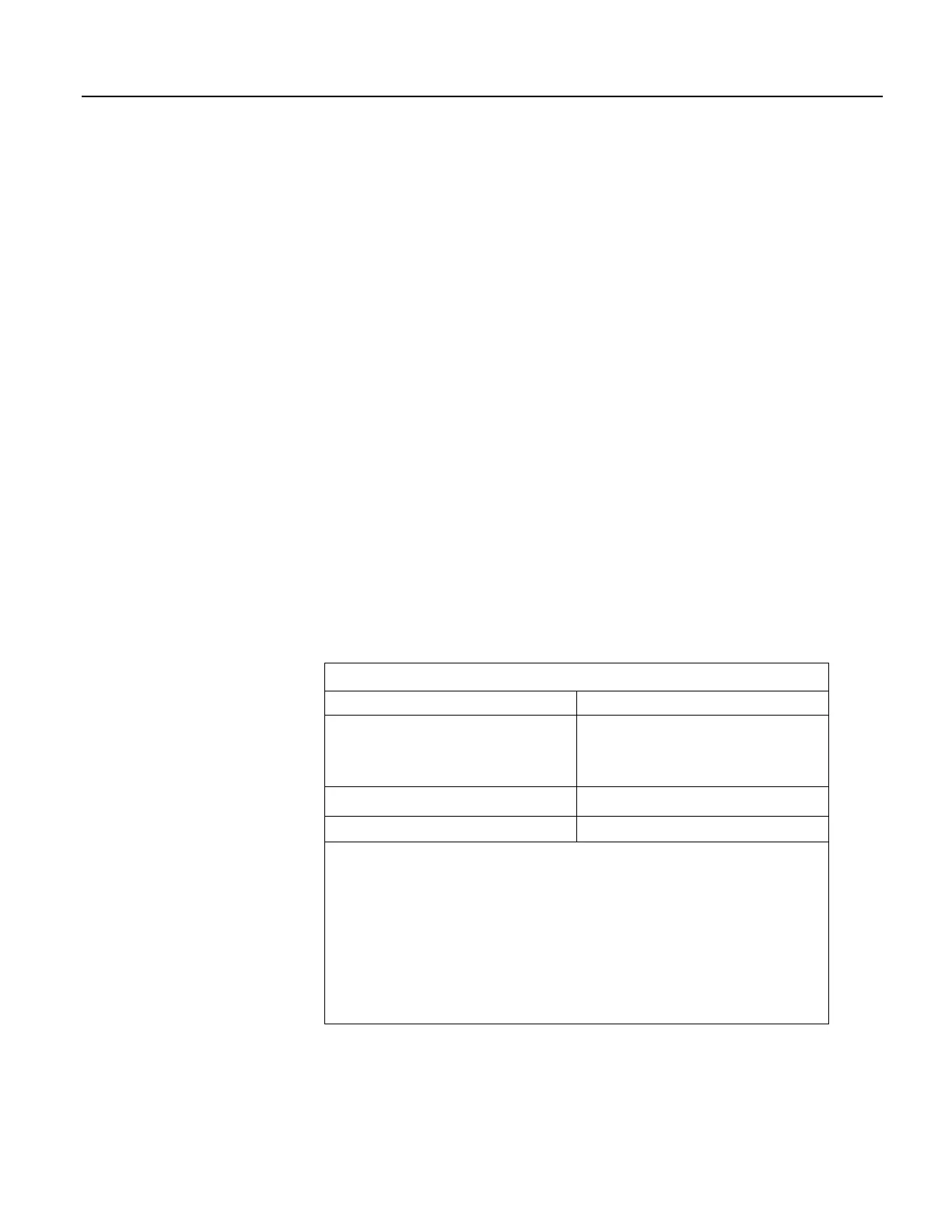
Table 64. Range-Code Option C Over-Voltages
Input Range Over-Voltage
±2.5 mV
±7.5 mV
±25 mV
±250 mV
300 mV
±2500 mV
C option with caveat
1
±5000 mV
C option not available
1
C results in the H terminal being briefly connected to a voltage greater than 2500 mV, while the
L terminal is connected to ground. The resulting common-mode voltage is 1250 mV, which is not
adequate to null residual common-mode voltage, but is adequate to facilitate a type of open-input
detect. This requires inclusion of an If / Then / Else statement in the CRBasic program to test the
results of the measurement. For example:
•The result of a VoltDiff() measurement using mV2500C as the Range code can be tested for a
result >2500 mV, which would indicate an open input.
•The result of the BrHalf() measurement, X, using the mV2500C range code can be tested for
values >1. A result of X > 1 indicates an open input for the primary measurement, V1, where X =
V1/Vx and Vx is the excitation voltage. A similar strategy can be used with other bridge
measurements.
322

 Loading...

