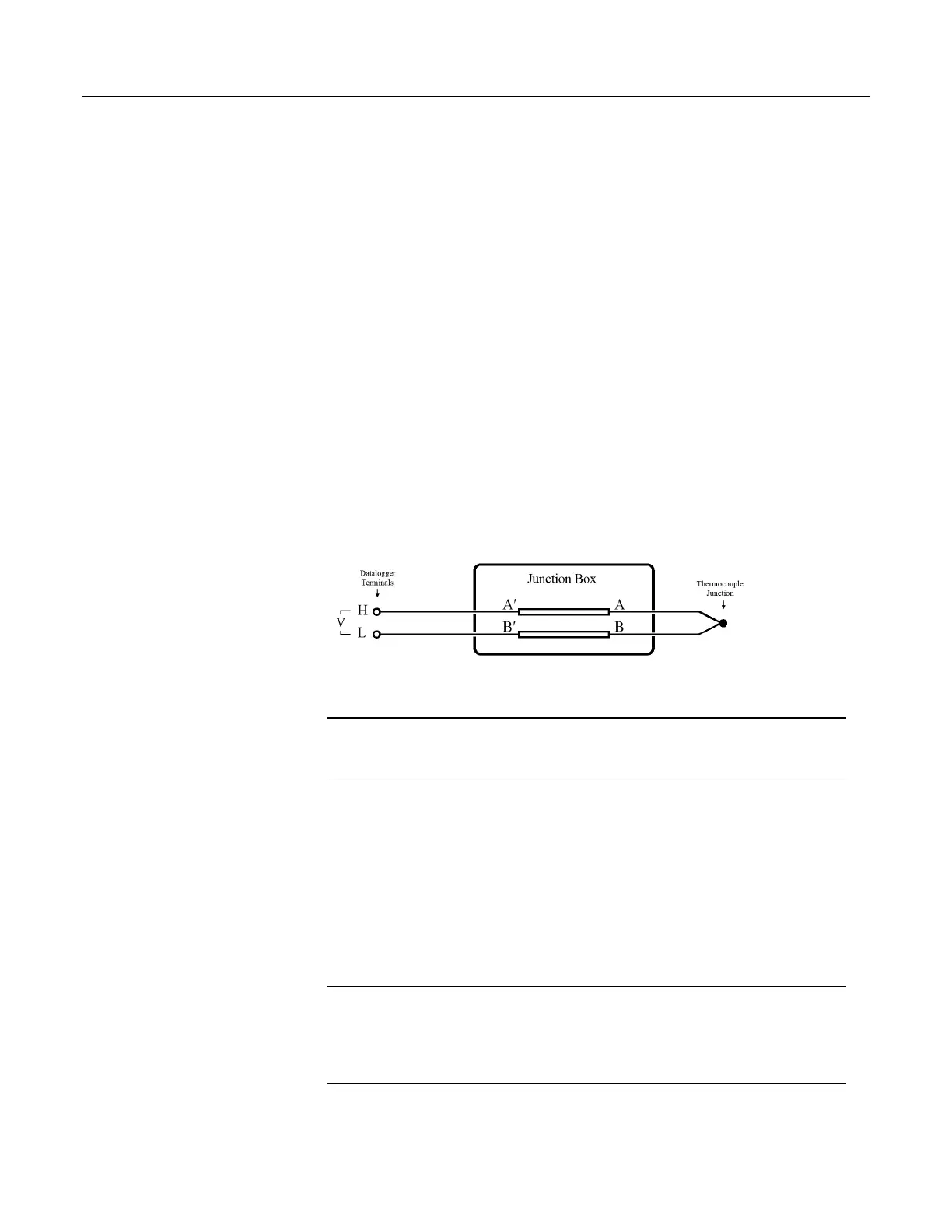
junction box wherein the reference junction is the CR1000. Terminal strips are a
different metal than the thermocouple wire. Thus, if a temperature gradient exists
between A and A' or B and B', the junction box will act as another thermocouple
in series, creating an error in the voltage measured by the CR1000. This
thermoelectric-offset voltage is also a factor when the junction box is used as the
reference junction. This offset can be minimized by making the thermal
conduction between the two points large and the distance small. The best solution
when extension-grade wire is being connected to thermocouple wire is to use
connectors which clamp the two wires in contact with each other.
When an external-junction box is also the reference junction, the points A, A', B,
and B' need to be very close in temperature (isothermal) to measure a valid
reference temperature, and to avoid thermoelectric-offset voltages. The box
should contain elements of high thermal conductivity, which will act to rapidly
equilibrate any thermal gradients to which the box is subjected. It is not necessary
to design a constant-temperature box. It is desirable that the box respond slowly to
external-temperature fluctuations. Radiation shielding must be provided when a
junction box is installed in the field. Care must also be taken that a thermal
gradient is not induced by conduction through the incoming wires. The CR1000
can be used to measure the temperature gradients within the junction box.
Figure 90. Diagram of a Thermocouple Junction Box
8.1.2.3 Current Measurements — Details
Related Topics:
• Current Measurements — Overview (p. 66)
• Current Measurements — Details
(p. 337)
For a complete treatment of current-loop sensors (4 to 20 mA, for example),
please consult the following publications available at www.campbellsci.com/app-
notes (http://www.campbellsci.com/app-notes):
• Current Output Transducers Measured with Campbell Scientific Dataloggers
(2MI-B)
• CURS100 100 Ohm Current Shunt Terminal Input Module
8.1.2.4 Resistance Measurements — Details
Related Topics:
• Resistance Measurements — Specifications
• Resistance Measurements — Overview
(p. 67)
• Resistance Measurements — Details (p. 337)
• Resistance Measurements — Instructions (p. 551)
337

 Loading...

