• The typical (and industry accepted) manufacturing error of thermocouple
wire
• The reference temperature
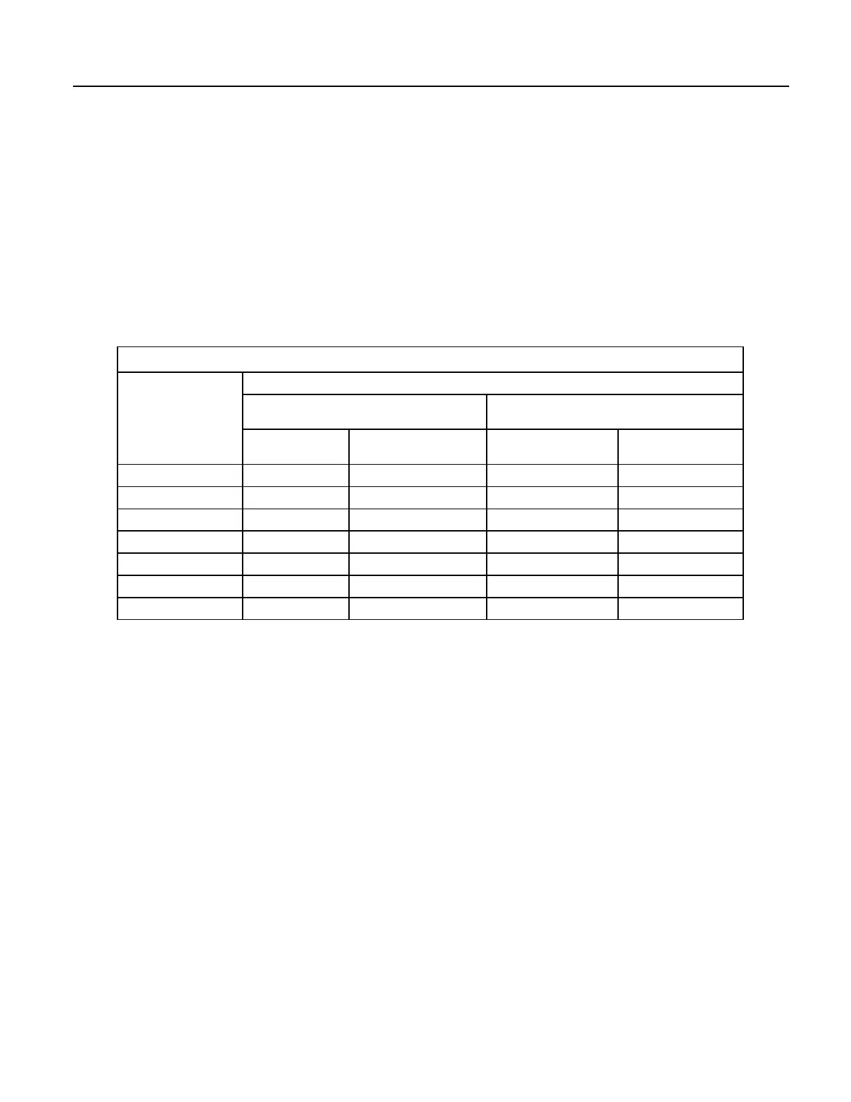
The table Thermocouple Error Examples
(p. 336) tabulates the relative magnitude of
these errors. It shows a worst case example where,
• A temperature of 45 °C is measured with a type-T thermocouple and all
errors are maximum and additive:
• Reference temperature is 25 °C, but it is indicating 25.1 °C.
• The terminal to which the thermocouple is connected is 0.05 °C cooler than
the reference thermistor (0.15 °C error).
Table 70. Thermocouple Error Examples
Source
Error: °C : % of Total Error
Single Differential
250 µs Integration
Reversing Differential
50/60 Hz Rejection Integration
ANSI TC Error
(1°C)
TC Error 1% Slope ANSI TC Error (1°C) TC Error 1% Slope
Reference Temperature 0.15° : 11.5% 0.15° : 29.9% 0.15° : 12.2% 0.15° : 34.7%
TC Output 1.0° : 76.8% 0.2° : 39.8% 1.0° : 81.1% 0.2° : 46.3%
Voltage Measurement 0.12° : 9.2% 0.12° : 23.9% 0.07° : 5.7% 0.07° : 16.2%
Noise 0.03° : 2.3% 0.03° : 6.2% 0.01° : 0.8% 0.01° : 2.3%
Reference Linearization 0.001° : 0.1% 0.001° : 0.2% 0.001° : 0.1% 0.001° : 0.25%
Output Linearization 0.001° : 0.1% 0.001° : 0.2% 0.001° : 0.1% 0.001° : 0.25%
Total Error 1.302° : 100% 0.502° : 100% 1.232° : 100% 0.432° : 100%
8.1.2.2.2 Use of External Reference Junction
An external junction in an insulated box is often used to facilitate thermocouple
connections. It can reduce the expense of thermocouple wire when measurements
are made long distances from the CR1000. Making the external junction the
reference junction, which is preferable in most applications, is accomplished by
running copper wire from the junction to the CR1000. Alternatively, the junction
box can be used to couple extension-grade thermocouple wire to the
thermocouples, with the PanelTemp() instruction used to determine the reference
junction temperature.
Extension-grade thermocouple wire has a smaller temperature range than standard
thermocouple wire, but it meets the same limits of error within that range. One
situation in which thermocouple extension wire is advantageous is when the
junction box temperature is outside the range of reference junction compensation
provided by the CR1000. This is only a factor when using type K thermocouples,
since the upper limit of the reference compensation polynomial fit range is 100 °C
and the upper limit of the extension grade wire is 200 °C. With the other types of
thermocouples, the reference compensation polynomial-fit range equals or is
greater than the extension-wire range. In any case, errors can arise if temperature
gradients exist within the junction box.
Figure Diagram of a Thermocouple Junction Box
(p. 337) illustrates a typical
336

 Loading...

