Section 5. System Overview
A measurement of current is accomplished through the use of external resistors to
convert current to voltage, then measure the voltage as explained in the section
Differential Measurements — Overview
(p. 66). The voltage is measured with the
CR1000 voltage measurement circuitry.
5.1.2.3 Resistance Measurements — Overview
Related Topics:
• Resistance Measurements — Specifications
• Resistance Measurements — Overview
(p. 67)
• Resistance Measurements — Details (p. 337)
• Resistance Measurements — Instructions (p. 551)
Many analog sensors use a variable-resistive device as the fundamental sensing
element. These elements are placed in a wheatstone bridge or related circuit. The
CR1000 can measure most bridge circuit configurations. A bridge measurement
is a special case voltage measurement. Examples include:
• Strain gage: resistance in a pressure-transducer strain gage correlates to a
water pressure.
• Position potentiometer: a change in resistance in a wind-vane potentiometer
correlates to a change in wind direction.
5.1.2.3.1 Voltage Excitation
Bridge resistance is determined by measuring the difference between a known
voltage applied to the excitation (input) arm of a resistor bridge and the voltage
measured on the output arm. The CR1000 supplies a precise-voltage excitation
via Vx terminals . Return voltage is measured on H/L] terminals configured for
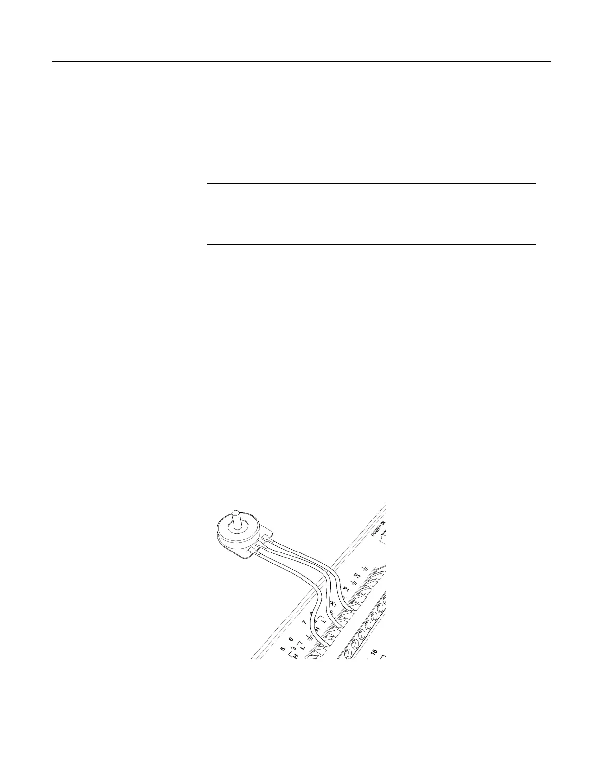
single-ended or differential input. Examples of bridge-sensor wiring using
voltage excitation are illustrated in figures Half-Bridge Wiring — Wind Vane
Potentiometer
(p. 67) and Full-Bridge Wiring — Pressure Transducer (p. 68).
Figure 21. Half-Bridge Wiring Example — Wind Vane Potentiometer
67

 Loading...

