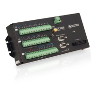
8.1.3.1 Pulse Measurement Terminals
P Terminals
• Input voltage range = –20 to 20 V
If pulse input voltages exceed ±20 V, third-party external-signal conditioners
should be employed. Contact a Campbell Scientific application engineer if
assistance is needed. Under no circumstances should voltages greater than 50 V
be measured.
C Terminals
• Input voltage range = –8 to 16 Vdc
C terminals configured for pulse input have a small 25 ns input RC-filter time
constant between the terminal block and the CMOS input buffer, which allows for
high-frequency pulse measurements up to 250 kHz and edge counting up to 400
kHz. The CMOS input buffer recognizes inputs ≥3.8 V as being high and inputs
≤1.2 V as being low.
Open-collector (bipolar transistors) or open-drain (MOSFET) sensors are
typically measured as frequency sensors. C terminals can be conditioned for open
collector or open drain with an external pull-up resistor as shown in figure Using
a Pull-up Resistor on C terminals
. The pull-up resistor counteracts an internal 100
kΩ pull-down resistor, allowing inputs to be pulled to >3.8 V for reliable
measurements.
8.1.3.2 Low-Level Ac Measurements — Details
Related Topics:
• Low-Level Ac Input Modules — Overview (p. 367)
• Low-Level Ac Measurements — Details (p. 352)
• Pulse Input Modules — Lists (p. 646)
Low-level ac (sine-wave) signals can be measured on P terminals. Sensors that
commonly output low-level ac include:
• Ac generator anemometers
Measurements include the following:
• Counts
• Frequency (Hz)
• Running average
Rotating magnetic-pickup sensors commonly generate ac voltage ranging from
thousandths of volts at low-rotational speeds to several volts at high-rotational
speeds. Terminals configured for low-level ac input have in-line signal
conditioning for measuring signals ranging from 20 mV RMS (±28 mV peak-to-
peak) to 14 V RMS (±20 V peak-to-peak).
352

 Loading...