Section 4. System Quickstart
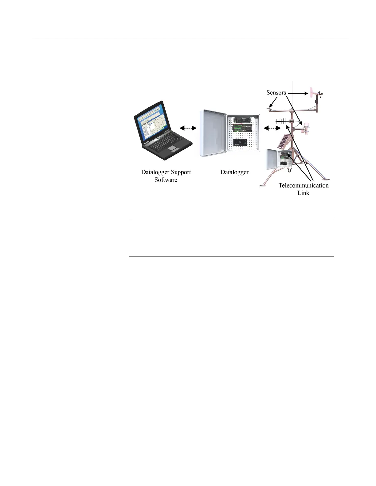
Figure 1. Data-Acquisition System Components
4.2 Sensors — Quickstart
Related Topics:
• Sensors — Quickstart (p. 42)
• Measurements — Overview
(p. 62)
• Measurements — Details
(p. 303)
• Sensors — Lists
(p. 649)
Sensors transduce phenomena into measurable electrical forms by modulating
voltage, current, resistance, status, or pulse output signals. Suitable sensors do
this accurately and precisely
(p. 533). Smart sensors have internal measurement and
processing components and simply output a digital value in binary, hexadecimal,
or ASCII character form. The CR1000, sometimes with the assistance of various
peripheral devices, can measure or read nearly all electronic sensor output types.
Sensor types supported include:
• Analog
o Voltage
o Current
o Thermocouples
o Resistive bridges
• Pulse
o High frequency
o Switch closure
o Low-level ac
• Period average
• Vibrating wire
• Smart sensors
o SDI-12
o RS-232
42

 Loading...

