Section 5. System Overview
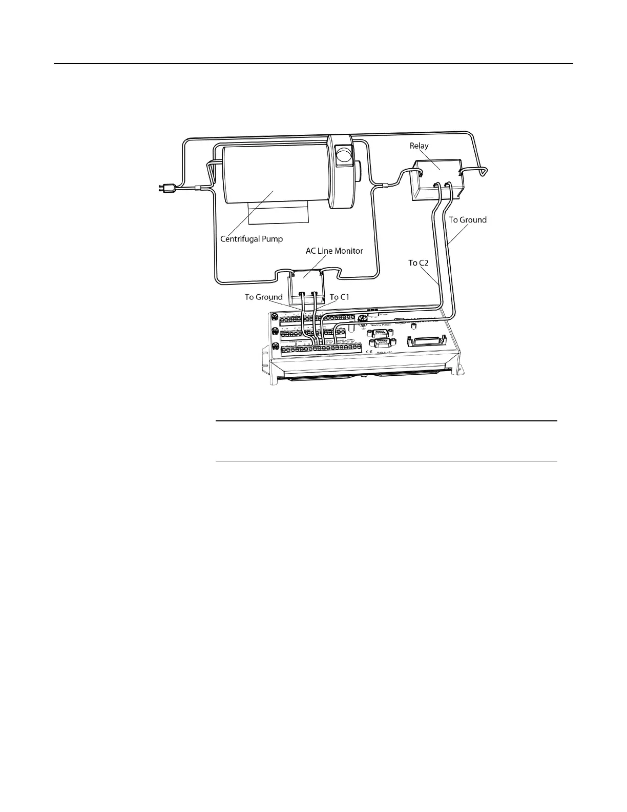
Figure 28. Control and Monitoring with C Terminals
5.3.2.2 Voltage Excitation — Overview
Related Topics:
• Voltage and Current Excitation — Specifications
• Voltage Excitation — Overview
(p. 79)
The CR1000 has several terminals designed to supply switched voltage to
peripherals, sensors, or control devices:
• Voltage Excitation (switched-analog output) — Vx terminals supply precise
voltage in the range of ±2500 mV. These terminals are regularly used with
resistive-bridge measurements. Each terminal will source up to ±25 mA.
•
• Digital I/O — C terminals configured for on / off and PWM (pulse width
modulation) or PDM (pulse duration modulation) on C4, C5 and C7.
• Switched 12 Vdc — SW12 terminals. Primary battery voltage under
program control to switch external devices (such as humidity sensors)
requiring nominal 12 Vdc. SW12 terminals can source up to 900 mA. See
the table Current Source and Sink Limits
(p. 103).
• Continuous Analog Output — available by adding a peripheral analog output
device available from Campbell Scientific. Refer to section Analog-Output
Modules
(p. 367) for information on available expansion modules.
79

 Loading...

