Section 5. System Overview
Most electronic sensors, whether or not they are supplied by Campbell Scientific,
can be connected directly to the CR1000.
Manuals that discuss alternative input routes, such as external multiplexers,
peripheral measurement devices, or a wireless sensor network, can be found at
www.campbellsci.com/manuals (http://www.campbellsci.com/manuals). You can
also consult with a Campbell Scientific application engineer.
This section discusses direct sensor-to-datalogger connections and applicable
CRBasic programming to instruct the CR1000 how to make, process, and store
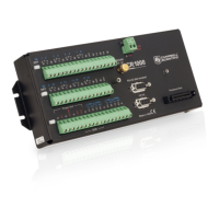
the measurements. The CR1000 wiring panel has terminals for the following
measurement inputs:
5.1.1 Time Keeping — Overview
Related Topics:
• Time Keeping — Overview (p. 75)
• Time Keeping — Details
(p. 303)
Measurement of time is an essential function of the CR1000. Time measurement
with the on-board clock enables the CR1000 to attach time stamps to data,
measure the interval between events, and time the initiation of control functions.
5.1.2 Analog Measurements — Overview
Related Topics:
• Analog Measurements — Overview (p. 63)
• Analog Measurements — Details
(p. 305)
Analog sensors output a continuous voltage or current signal that varies with the
phenomena measured. Sensors compatible with the CR1000 output a voltage.
Current output can be made compatible with a resistive shunt.
Sensor connection is to H/L] terminals configurable for differential (DIFF) or
single-ended (SE) inputs. For example, differential channel 1 is comprised of
terminals 1H and 1L, with 1H as high and 1L as low.
5.1.2.1 Voltage Measurements — Overview
Related Topicss:
• Voltage Measurements — Specifications
• Voltage Measurements — Overview
(p. 63)
• Voltage Measurements — Details
(p. 305)
• Maximum input voltage range: ±5000 mV
• Measurement resolution range: 0.67 µV to 1333 µV
Single-ended and differential connections are illustrated in the figures Analog
Sensor Wired to Single-Ended Channel #1
(p. 64) and Analog Sensor Wired to
Differential Channel #1
(p. 64). Table Differential and Single-Ended Input
Terminals
(p. 65) lists CR1000 analog-input channel termnal assignments.
Conceptually, analog-voltage sensors output two signals: high and low.
Sometimes, the low signal is simply sensor ground. A single-ended measurement
measures the high signal with reference to ground, with the low signal tied to
63

 Loading...