EasyManuals Logo

Campbell CR1000 User Manual

Campbell CR1000
678 pages
To Next Page IconTo Next Page
To Previous Page IconTo Previous Page
Page #77 background imageLoading...
Page #77 background image
Section 5. System Overview
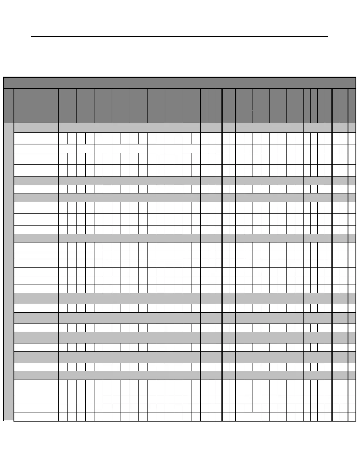
Table 4. CR1000 Wiring Panel Terminal Definitions
Labels
SE 1 2 3 4 5 6 7 8 9 10 11 12 13 14 15 16
COM1 COM2 COM3 COM4
DIFF
┌ 1 ┐ ┌ 2 ┐ ┌ 3 ┐ ┌ 4 ┐ ┌ 5 ┐ ┌ 6 ┐ ┌ 7 ┐ ┌ 8 ┐
T
x
R
x
T
x
R
x
T
x
R
x
T
x
R
x
H L H L H L H L H L H L H L H L
VX1
VX2
VX3
P1
P2
C1
C2
C3
C4
C5
C6
C7
C8
5V
12V
12V
SW-12
RS-
CS I/O
Max
Function
Analog Input
Single-ended
1
6
Differential (high/low)
8
Analog period average
1
6
Vibrating wire
2
1
6
Analog Output
Switched Precision Voltage
3
Pulse Counting
Switch closure
1
0
High frequency
1
0
Low-level Vac
2
Digital I/O
Control
8
Status
8
General I/O (TX,RX)
4
Pulse-width modulation
8
Timer I/O
8
Interrupt
8
Continuous Regulated
3
5 Vdc
1
Continuous Unregulated
3
12 Vdc
2
Switched Regulated
3
5 Vdc
8
Switched Unregulated
3
12 Vdc
1
UART
True RS-232 (TX/RX)
4
2
TTL RS-232 (TX/RX)
4
SDI-12
4
SDM (Data/Clock/Enable)
1
77

Table of Contents

Questions and Answers:

Question and Answer IconNeed help?

Do you have a question about the Campbell CR1000 and is the answer not in the manual?

Campbell CR1000 Specifications

General IconGeneral
Power Requirements9.6 to 16 VDC
Data Logger Operating SystemCRBasic
Memory4 MB
Analog Inputs16 single-ended or 8 differential
Analog Input Resolution13 bits
Analog Input Range+/-2.5V
Digital I/O8
Pulse Counters2
Communication PortsRS-232
Operating Temperature-25°C to +50°C
Pulse Channels4

Related product manuals