Section 4. System Quickstart
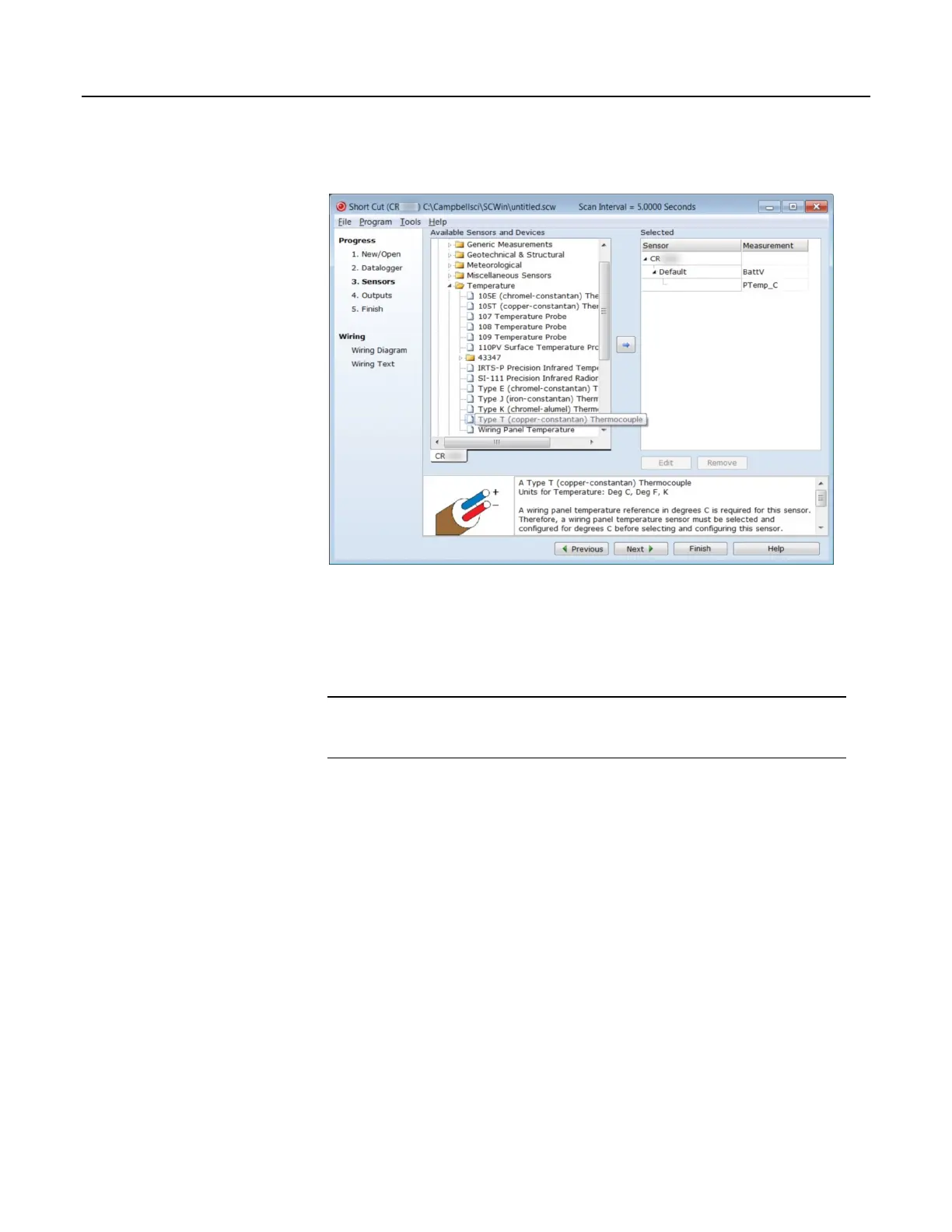
Figure 5. Short Cut Temperature Sensor Folder
4.7.4.2 Procedure: (Short Cut Steps 6 to 7)
6. Double-click Type T (copper-constantan) Thermocouple to add it into the
Selected column. A dialog window is presented with several fields. By
immediately clicking OK, you accept default options that include selection of
1 sensor and PTemp_C as the reference temperature measurement.
Note BattV (battery voltage) and PTempC (wiring panel temperature) are
default measurements. During operation, battery and temperature should be
recorded at least daily to assist in monitoring system status.
7. At the left portion of the main Short Cut window, click Wiring Diagram.
Attach the physical type-T thermocouple to the CR1000 as shown in the
diagram. Click on 3. Sensors in the left portion of the window to return to the
sensor selection screen.
51

 Loading...

