Section 5. System Overview
5.1.3.3 Pulse Sensor Wiring
Read More See the section Pulse Measurement Tips (p. 356)
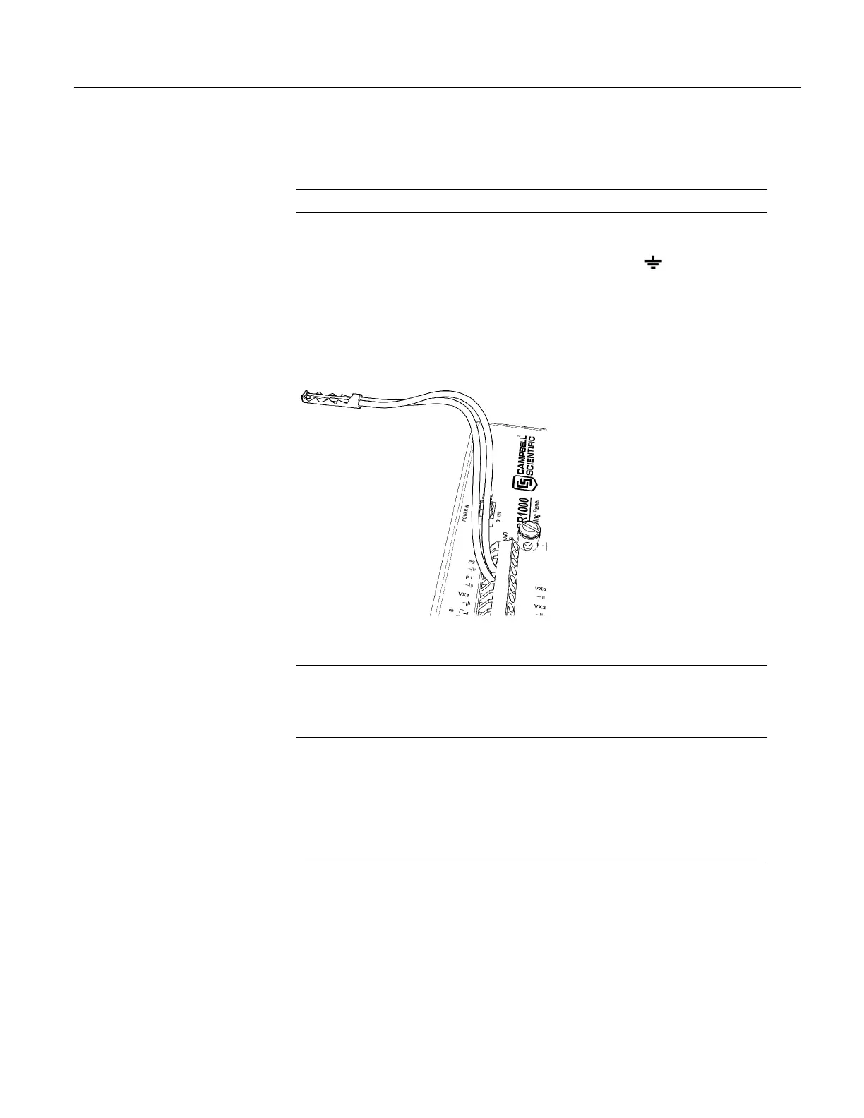
An example of a pulse sensor connection is illustrated in figure Pulse-Input
Wiring Example — Anemometer Switch
(p. 70). Pulse sensors have two active
wires, one of which is ground. Connect the ground wire to a
(signal ground)
terminal. Connect the other wire to a P terminal. Sometimes the sensor will
require power from the CR1000, so there may be two power wires — one of
which will be power ground. Connect power ground to a G terminal. Do not
confuse the pulse wire with the positive-power wire, or damage to the sensor or
CR1000 may result. Some switch-closure sensors may require a pull-up resistor.
Figure 24. Pulse-Input Wiring Example — Anemometer
5.1.4 Period Averaging — Overview
Related Topics:
• Period Averaging — Specifications
• Period Averaging — Overview
(p. 70)
• Period Averaging — Details
(p. 360)
The CR1000 can measure the period of an analog signal.
Numbered SE terminals are configurable for period average:
• Voltage gain: 1, 10, 33, 100
• Maximum frequency: 200 kHz
• Resolution: 136 ns
Note Both pulse-count and period-average measurements are used to measure
frequency output sensors. Yet pulse-count and period-average measurement
methods are different. Pulse-count measurements use dedicated hardware — pulse
count accumulators, which are always monitoring the input signal, even when the
CR1000 is between program scans. In contrast, period-average measurement
instructions only monitor the input signal during a program scan. Consequently,
pulse-count scans can usually be much less frequent than period-average scans.
Pulse counters may be more susceptible to low-frequency noise because they are
70

 Loading...

