thermocouple.
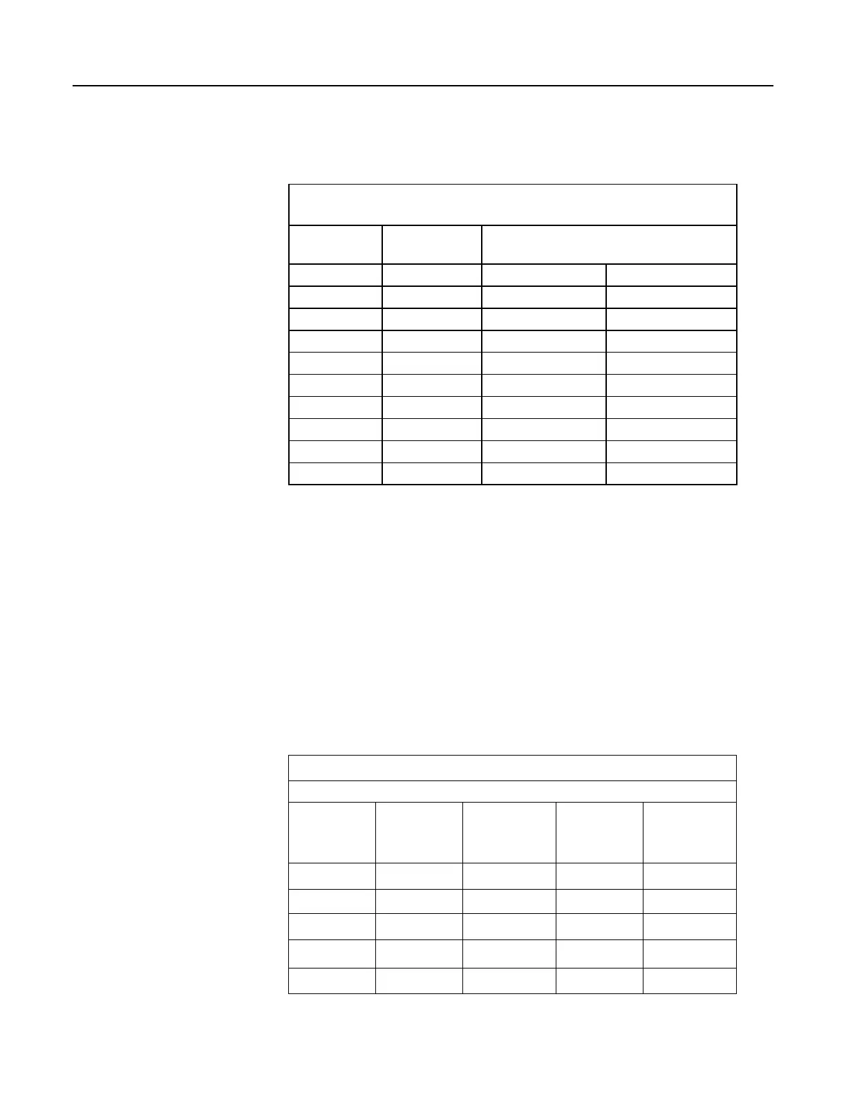
Table 66. Limits of Error for Thermocouple Wire (Reference
Junction at 0°C)
Thermocouple
Temperature
Limits of Error
(Whichever is greater)
Type Range °C Standard Special
T –200 to 0 ± 1.0 °C or 1.5%
0 to 350 ± 1.0 °C or 0.75% ± 0.5 °C or 0.4%
J 0 to 750 ± 2.2 °C or 0.75% ± 1.1 °C or 0.4%
E –200 to 0 ± 1.7 °C or 1.0%
0 to 900 ± 1.7 °C or 0.5% ± 1.0 °C or 0.4%
K –200 to 0 ± 2.2 °C or 2.0%
0 to 1250 ± 2.2 °C or 0.75% ± 1.1 °C or 0.4%
R or S 0 to 1450 ± 1.5 °C or 0.25% ± 0.6 °C or 0.1%
B 800 to 1700 ± 0.5% Not Established.
Thermocouple Voltage Measurement Error
Thermocouple outputs are extremely small — 10 to 70 µV per °C. Unless high
resolution input ranges are used when programming, the CR1000, accuracy and
sensitivity are compromised. Table Voltage Range for Maximum Thermocouple
Resolution
(p. 331) lists high resolution ranges available for various thermocouple
types and temperature ranges. The following four example calculations of
thermocouple input error demonstrate how the selected input voltage range
impacts the accuracy of measurements. Figure Input Error Calculation
(p. 332)
shows from where various values are drawn to complete the calculations. See
Measurement Accuracy
for more information on measurement accuracy and
accuracy calculations.
When the thermocouple measurement junction is in electrical contact with the
object being measured (or has the possibility of making contact) a differential
measurement should be made to avoid ground looping.
Table 67. Voltage Range for Maximum Thermocouple Resolution
Reference temperature at 20°C
TC Type and
Temperature
Range (°C)
Temperature
Range (°C)
for ±2.5 mV
Input Range
Temperature
Range (°C)
for ±7.5 mV
Input Range
Temperature
Range (°C)
for ±25 mV
Input Range
Temperature
Range (°C)
for ±250 mV
Input Range
T: –270 to 400 –45 to 75 –270 to 180 –270 to 400 not used
E: –270 to 1000 –20 to 60 –120 to 130 –270 to 365 >365
K: –270 to 1372 –40 to 80 –270 to 200 –270 to 620 >620
J: –210 to 1200 –25 to 65 –145 to 155 –210 to 475 >475
B: –0 to 1820 0 to 710 0 to 1265 0 to 1820 not used
331

 Loading...

