Section 10. Troubleshooting
Charging Regulator with ac or dc Transformer Test
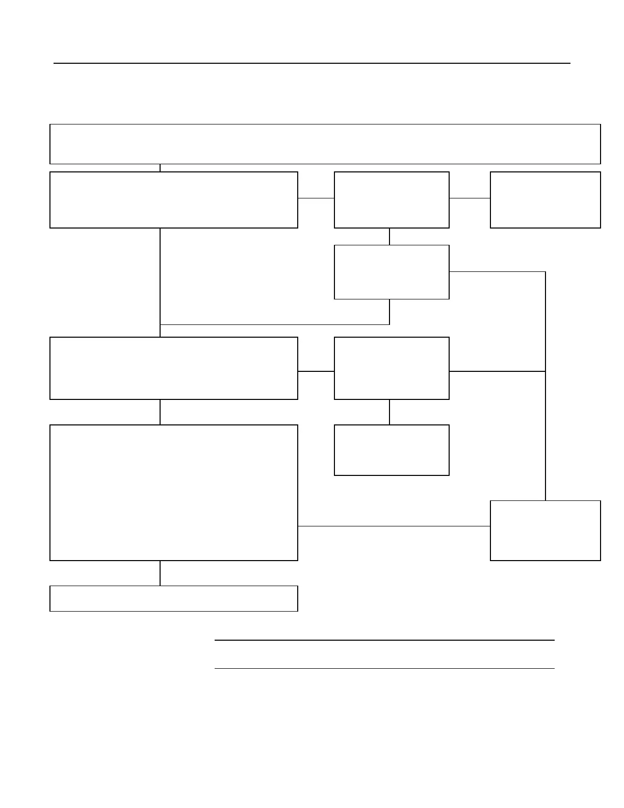
Disconnect any wires attached to the 12V and G (ground) terminals on the PS100 or CH100 charging regulator. Unplug any batteries. Connect the power input ac or dc transformer to the
two CHG terminals. Polarity of the inputs does not matter. Only the transformer should be connected. Set the charging-regulator power switch to OFF. Connect the transformer to mains
power.
Transformer Test
Determine whether the transformer output is ac or dc voltage (labeling on the
transformer usually identifies the output voltage type). Set a voltmeter to read that
type of voltage. Measure transformer output across the two transformer leads by
placing a voltmeter lead on one CHG terminal, and the other lead on the other
CHG terminal. Is the output 17 to 22 volts?
Taking care not to short the
transformer leads, remove the leads
from the charging regulator.
Measure transformer output across
the two leads. Is the output 17 to 22
Vac / Vdc?
The transformer is damaged and
should be replaced.
No No
Yes
Yes
Reconnect the power source
(transformer / solar panel) to the
CHG terminals on the charging
regulator. Measure the voltage
between the two CHG terminals. Is
the voltage ≥ 17 Vdc / Vac?
No
Yes
5 kΩ Load Test
1) Place a 5 kΩ resistor between a 12V terminal and a G (ground) terminal on the
charging regulator.
2) Switch the power switch to ON.
3) Measure the dc voltage across the resistor.
Is the measured voltage 13.3 to 14.1 V?
Measure the voltage between the two
pins in a battery-connection
receptacle. Is the voltage 10.0 to
15.5 Vdc?
No No
Yes
Yes
50 Ω Load Test
1) Switch the power switch to
OFF.
2) Disconnect the power source (transformer / solar panel).
3) Remove the 5 kΩ resistor
4) Place a 50 Ω, 1 W resistor between a
12V terminal and a G (ground) terminal on
the charging regulator.
5) Reconnect the power source and then switch the power switch to
ON.
7) Measure the voltage across the ends of the resistor.
Is the voltage 13.0 to 14.0 Vdc (13.3 if circuit just adjusted)?
8) Switch the power switch to
OFF.
NOTE The resistor will get HOT in just a few seconds. After measuring the
voltage, switch the power switch to
OFF and allow the resistor to cool before
removing it.
See Adjusting Charging Voltage (p.
499) to calibrate the charging
regulator, or return the charging
regulator to Campbell Scientific for
calibration.
Get Repair Authorization
The charging regulator is damaged
and should be repaired or replaced.
No
Yes
Test Completed
The charger is functioning properly. Remove the 50 Ω resistor.
10.9.3.4 Adjusting Charging Voltage
Note Campbell Scientific recommends that a qualified electronic technician
perform the following procedure.
The procedure outlined in this flow chart tests and adjusts PS100 and CH100
charging regulators. If a need for repair or calibration is indicated after following
the procedure, see Warranty and Assistance
(p. 3) for information on sending items
to Campbell Scientific.
499

 Loading...

