Section 5. System Overview
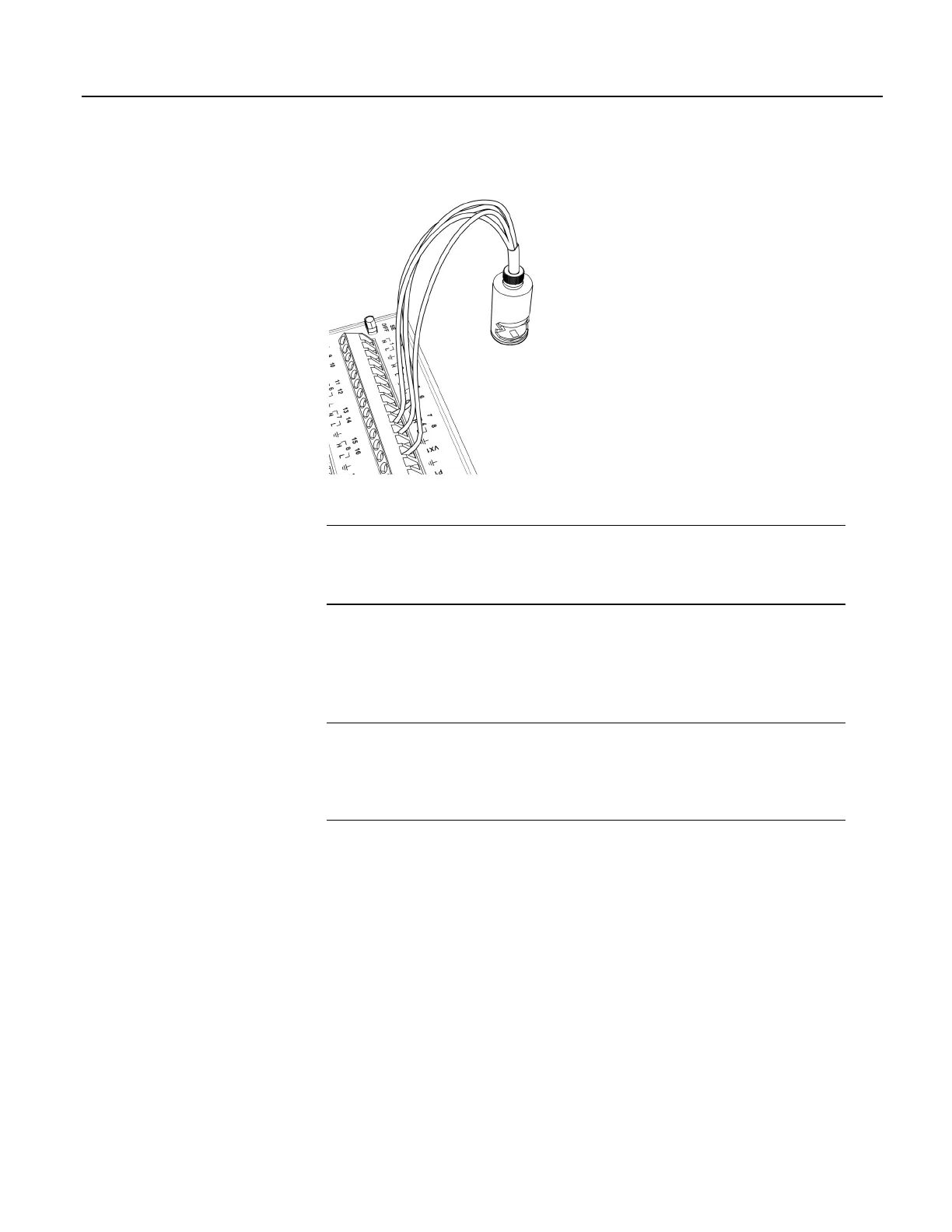
Figure 22. Full-Bridge Wiring Example — Pressure Transducer
5.1.2.4 Strain Measurements — Overview
Related Topics:
• Strain Measurements — Overview (p. 68)
• Strain Measurements — Details
(p. 342)
• FieldCalStrain() Examples
(p. 223)
Strain gage measurements are usually associated with structural-stress analysis.
When making strain measurements, please first consult with a Campbell Scientific
application engineer.
5.1.3 Pulse Measurements — Overview
Related Topics
• Pulse Measurements — Specifications
• Pulse Measurements — Overview
(p. 68)
• Pulse Measurements — Details
(p. 349)
• Pulse Measurements — Instructions
(p. 553)
The output signal generated by a pulse sensor is a series of voltage waves. The
sensor couples its output signal to the measured phenomenon by modulating wave
frequency. The CR1000 detects the state transition as each wave varies between
voltage extremes (high-to-low or low-to-high). Measurements are processed and
presented as counts, frequency, or timing data.
P terminals are configurable for pulse input to measure counts or frequency from
the following signal types:
• High-frequency 5 Vdc square-wave
• Switch closure
• Low-level ac
C terminals configurable for input for the following:
• State
• Edge counting
68

 Loading...

