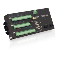
Section 5. System Overview
1
Terminal expansion modules are available.
2
Static, frequency-domain measurement
3
Check the table Current Source and Sink Limits (p. 103)
4
Requires an interfacing device for sensor input. See the table CS I/O to RS-232 Interfaces (p. 651).
5.3.2.1 Switched Voltage Output — Overview
Related Topics:
• Switched Voltage Output — Specifications
• Switched Voltage Output — Overview
(p. 78)
• Switched Voltage Output — Details
(p. 103)
• PLC Control — Overview (p. 74)
• PLC Control — Details (p. 244)
• PLC Control Modules — Overview (p. 368)
• PLC Control Modules — Lists (p. 648)
• PLC Control — Instructions (p. 562)
C terminals are selectable as binary inputs, control outputs, or communication
ports. See the section Measurement — Overview
(p. 62) for a summary of
measurement functions. Other functions include device-driven interrupts,
asynchronous communications and SDI-12 communications. Table CR1000
Terminal Definitions
(p. 76) summarizes available options.
Figure Control and Monitoring with C Terminals
(p. 79) illustrates a simple
application wherein a C terminal configured for digital input and another
configured for control output are used to control a device (turn it on or off) and
monitor the state of the device (whether the device is on or off).
78

 Loading...